Multifunctional combined crane

A combined, crane technology, applied in the direction of cranes, trolley cranes, load hanging components, etc., can solve the problem that it cannot adapt to multi-function, multi-purpose, multi-working conditions, multi-lifting weight, bridge cranes cannot be used as gantry cranes, The door machine cannot be used as a bridge machine, etc.

Active Publication Date: 2016-07-27
POWERCHINA SEPCO1 ELECTRIC POWER CONSTR CO LTD
View PDF6 Cites 11 Cited by
  • Summary
  • Abstract
  • Description
  • Claims
  • Application Information

AI Technical Summary

Problems solved by technology

The structure of the bridge crane and the door crane is different, and there is no commonality between them. The bridge crane cannot be used as a door crane, and the door crane cannot be used as a bridge crane; Two combined structures, but the single beam and the double beam cannot be split, combined, an

Method used


Image

  • Multifunctional combined crane
  • Multifunctional combined crane
  • Multifunctional combined crane

Examples


Embodiment 1

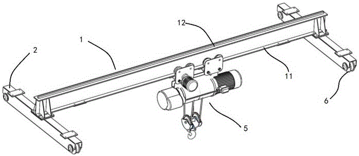
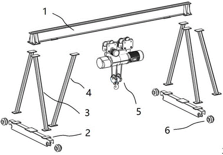
[0025] Such as Figure 1 to Figure 3 As shown, the present embodiment is a bridge-gate type conversion combined crane with a single girder, and the specific structure is:

[0026] A multifunctional combined crane, including a main beam 1 and a trolley for lifting heavy objects; the trolley is a lower trailer 5, and the main beam 1 is provided with a track I11 for the lower trailer 5 to travel and a trolley for the upper vehicle 8. The running track II12; the end of the main beam 1 is vertically provided with an end beam 2 for driving it to walk, and the front and rear ends of the end beam 2 are respectively provided with wheels 6 . The main beam 1 and the end beam 2 are detachably connected or / and connected by two legs A3 used to support the main beam 1, and the upper and lower ends of the legs A3 are connected to the main beam 1 and the end beam 2 There are detachable connections between them. In this field, such as figure 2 This arrangement position and arrangement manne...

Embodiment 2

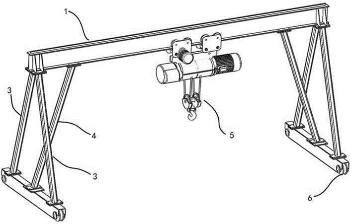
[0031] Such as Figure 4 As shown, this embodiment is a single-girder gantry crane. On the basis of the single-girder bridge crane involved in Embodiment 1, the form of the outrigger changes after conversion: between the main girder 1 and the end girder 2 at its left end There are two outriggers B4 that are detachably connected inclined relative to the main beam 1, combined with Figure 4 , the two outriggers B4 are arranged in a V shape, and there is no outrigger B4 between the main beam 1 and the end beam 2 at its right end. With such a design, it can be used in occasions where the horizontal span of the door machine is larger.

Embodiment 3

[0033] Such as Figure 5 to Figure 9 As shown, the present embodiment is a double-girder bridge-gate conversion combined crane, and the specific structure is:

[0034] A multifunctional combined crane, including a main beam 1 and a trolley for lifting heavy objects; the trolley is an upper trolley 8, and the main beam 1 is provided with a track I11 for the lower trailer 5 to travel and a trolley for the upper trolley. 8. The track II12 for walking; the end of the main beam 1 is vertically provided with an end beam 2 for driving it to walk, and the front and rear ends of the end beam 2 are respectively provided with wheels 6; the main beam 1 and the end beam 2 are detachably connected or / and connected by two outriggers A3 for supporting the main beam 1, and the upper and lower ends of the outrigger A3 are detachably connected with the main beam 1 and the end beam 2 respectively.

[0035] In the above-mentioned multifunctional combined crane, there are two main girders 1, and t...


PUM


Abstract

The invention relates to a multifunctional combined crane capable of performing conversion between a bridge crane and a gantry crane and conversion between a single-beam crane and a double-beam crane, and belongs to the field of lifting machinery. The multifunctional combined crane comprises a main beam and a trolley for lifting a weight; the trolley is a lower trailer or/and an upper travelling crane; the main beam is provided with a rail I for the lower trailer to walk and a rail II for the upper travelling crane to walk; end beams for driving the main beam to walk are perpendicularly arranged at the end part of the main beam; wheels are arranged at the front and back ends of each end beam; the main beam and each end beam are detachably connected or/and through two support legs A for supporting the main beam; and the upper and lower ends of the support legs A are detachably connected with the main beam and each end beam.

Description

technical field [0001] The invention relates to a multifunctional combined crane capable of bridge-gate conversion and single-double girder conversion, belonging to the field of hoisting machinery. Background technique [0002] Traditional bridge cranes and gantry cranes are mostly integral or welded in structure, and the connecting beams and outriggers are not interchangeable. Gantry cranes are actually bridge cranes with outriggers. The biggest difference between them and bridge cranes is that they rely on outriggers to run on ground rails, while the lifting mechanism and operating mechanism are basically the same. The structure of the bridge crane and the door crane is different, and there is no commonality between them. The bridge crane cannot be used as a door crane, and the door crane cannot be used as a bridge crane; Two combined structures, but the single beam and the double beam cannot be split, combined, and interchanged, so the structure and performance are singl...

Claims


Application Information

Patent Timeline
IPC IPC(8): B66C19/00B66C6/00B66C7/08
CPCB66C6/00B66C7/08B66C19/00B66C2700/0321B66C2700/035
Inventor 王永新李鹏举韩吉超庞继勇
Owner POWERCHINA SEPCO1 ELECTRIC POWER CONSTR CO LTD
Why Eureka
Try Eureka