Limiting antitheft alarming device for building sliding window and use method of limiting antitheft alarming device

A technology of anti-theft alarm and sliding window, which is applied in the direction of anti-theft alarm, alarm, wing fan suspension device, etc., can solve the problems of unsafe factors, cumbersome, large engineering quantity and other problems in the upper residential buildings, and achieve the goal of preventing accidental fall accidents Effect

Inactive Publication Date: 2016-07-27
王肖毅
View PDF5 Cites 6 Cited by
  • Summary
  • Abstract
  • Description
  • Claims
  • Application Information

AI Technical Summary

Problems solved by technology

[0002] The traditional anti-theft windows of buildings are to install metal steel pipe fence windows, which are not beautiful but also easy for thieves to climb, which adds unsafe factors to the upper houses
In addition, when emergencies such as earthquakes and fires occur, the fence windows will block people's escape routes from the windows, delay the escape opportunity, and bring unpredictable losses to people.
[0003] In the building environment where the sliding window limit fixing device is not installed, there are frequent incidents of children falling from the building due to the opening of the sliding window at will. This kind of residence is also prone to incidents such as break-in by outsiders and theft.
[0004] Installing intelligent security automatic alarm devices at home, because the power supply needs to be laid out in advance, for the houses that have been decorated, the installation of intelligent security alarm devices requires a large amount of engineering, and the external wiring is not beautiful, which is cumbersome.

Method used


Image

  • Limiting antitheft alarming device for building sliding window and use method of limiting antitheft alarming device
  • Limiting antitheft alarming device for building sliding window and use method of limiting antitheft alarming device
  • Limiting antitheft alarming device for building sliding window and use method of limiting antitheft alarming device

Examples


Embodiment Construction

[0030] Below in conjunction with accompanying drawing and specific embodiment, further illustrate the present invention, should be understood that these embodiments are only for illustrating the present invention and are not intended to limit the scope of the present invention, after having read the present invention, those skilled in the art will understand various aspects of the present invention Modifications in equivalent forms all fall within the scope defined by the appended claims of this application.

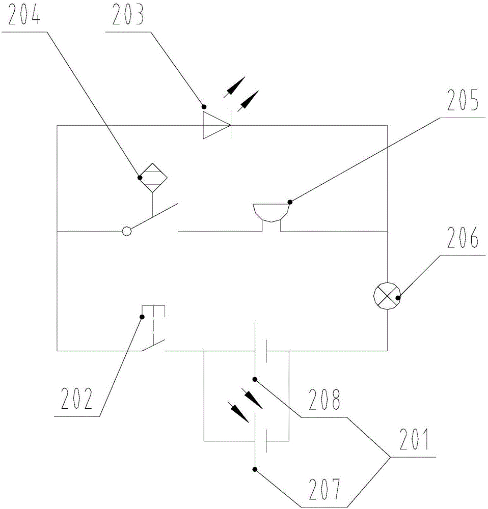
[0031] A limit anti-theft alarm device for a sliding window of a building, comprising a limit lock in the mechanical structure part, an electronic alarm in the electrical circuit part, and a mechanical structure linkage circuit structure.

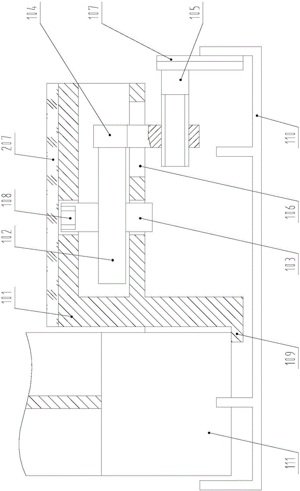
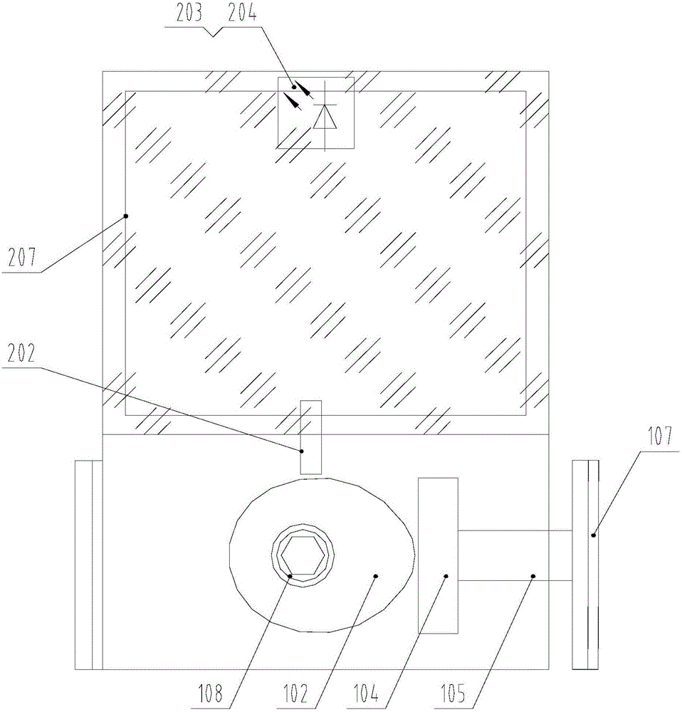
[0032] as attached figure 1 , 2 As shown, the limit lock includes a lock body frame 101 , a cam 102 , a shaft 103 , a slider 104 , a support plate 105 , a rubber plate 107 , and a locking nut 108 . Cam 102 is fixed with axle 103, an...


PUM


Abstract

The invention discloses a limiting antitheft alarming device for a building sliding window and a use method of the limiting antitheft alarming device. The limiting antitheft alarming device comprises a limiting lock and an electronic alarm. A mechanical structure of the limiting lock and an electric appliance structure of the electronic alarm are combined, and the mechanical structure is linked with the electric appliance structure, so that the purposes of limiting locking of the sliding window and detection of a stranger bursting into a room by breaking the window are effectively achieved; the limiting lock conducts self locking on a sliding block through a cam, the position of the sliding window is fixed, moving of the sliding window is limited, a child in the room is prevented from opening the window at will, and accidental falling accidents are prevented; and power is supplied to the electronic alarm through a photovoltaic cell panel, a special external power source is not needed, laser induction is achieved, when an emitted laser beam is blocked, loud alarming sounds can be emitted out, and therefore the stranger bursting into the room can be detected, and antitheft alarming can be conducted.

Description

technical field [0001] The invention relates to the field of building window safety, in particular to a position-limiting anti-theft alarm device installed on a sliding window of a building and a use method thereof. Background technique [0002] The traditional anti-theft window of buildings is to install metal steel pipe fence windows. This kind of fence windows is not only unsightly but also easy for thieves to climb, which adds unsafe factors to upper-floor residences. In addition, when emergencies such as earthquakes and fires occur, the fence windows will block people's escape routes from the windows, delay the escape opportunity, and bring unpredictable losses to people. [0003] In the building environment where the sliding window limit fixing device is not installed, there are frequent incidents of children falling from the building due to the opening of the sliding window at will. This kind of residence is also prone to incidents such as break-in by outsiders and th...

Claims


Application Information

Patent Timeline
Patent Type & Authority Applications(China)
IPC IPC(8): E05C17/60G08B13/183
CPCE05C17/60G08B13/183
Inventor 王肖毅
Owner 王肖毅
Why Eureka
Try Eureka