Backlight module and liquid crystal display device

A liquid crystal display device and backlight module technology, which is applied in optics, nonlinear optics, instruments, etc., can solve the problem of inability to meet the technical requirements of liquid crystal panels, regional light leakage, and easy detachment of the liquid crystal panel and the upper surface of the middle frame support arm. question

Active Publication Date: 2019-09-27
HISENSE VISUAL TECH CO LTD
View PDF7 Cites 0 Cited by
  • Summary
  • Abstract
  • Description
  • Claims
  • Application Information

AI Technical Summary

Problems solved by technology

[0004] As the size of the liquid crystal panel becomes larger, the D value is too small to meet the technical requirements for the liquid crystal panel 210 to be stably fixed on the middle frame 260. Further, the liquid crystal panel is easily detached from the upper surface of the middle frame support arm. Light leakage problem in some areas

Method used


Image

  • Backlight module and liquid crystal display device
  • Backlight module and liquid crystal display device
  • Backlight module and liquid crystal display device

Examples


Embodiment 1

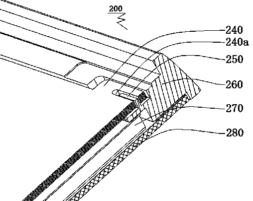
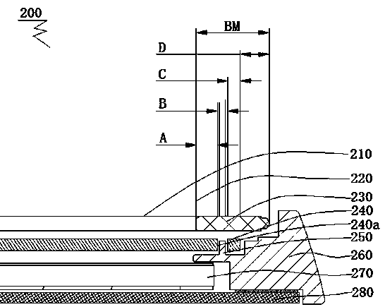
[0046] like Figure 2a~Figure 10 As shown, the backlight module liquid crystal display device provided by the first embodiment of the present invention will be described in detail below with reference to the accompanying drawings. In addition to the backlight module of the liquid crystal display device provided by the embodiment of the present invention, the Figure 2a~Figure 10 In addition to the structure shown, it also includes at least a backlight source, a reflective sheet, and the like. Regarding other components of the backlight module of the liquid crystal display device according to the embodiment of the present invention, those skilled in the art can refer to the backlight modules of the liquid crystal display device disclosed in the prior art. The specific structure is not limited in the present invention.

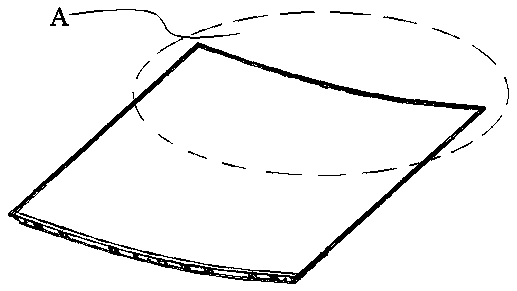
[0047] Figure 2a is an overall view of the liquid crystal display device of the present invention; Figure 2b for Figure 2a A partial enlarged view of par...

Embodiment 2

[0065] The second embodiment is a modification of the first embodiment, which is combined with reference to Figure 11 , Figure 12 and Figure 13 The difference from the first embodiment is that the second part 123b of the bracket is a single flat plate 1231b, and the flat plate 1231b includes a top surface 12311b and a bottom surface 12312b; correspondingly, the lower surface of the middle frame 122 is a plane 12232a.

[0066] Incorporate references Figure 11 , Figure 14a and Figure 14b As shown, the second part 123b is fixedly connected to the flat surface 12232a of the lower surface of the middle frame through the top surface 12331b of the flat plate, and the fixing method can be selected by sticking or screwing, and can also be clamped, which is not limited in the present invention. .

[0067] continue as Figure 11 As shown, the back plate 124 is fixedly connected to the bottom surface 12312b of the flat plate, and the fixing method can be selected by sticking o...


PUM

PropertyMeasurementUnit
thicknessaaaaaaaaaa

Abstract

The invention discloses a backlight module and relates to the technical field of display, in particular to the backlight module and a liquid crystal display device. The backlight module comprises a middle frame forming a rectangular frame, a support, a diaphragm and a light guide plate. The middle frame comprises a side wall and a supporting part extending in the perpendicular direction of the side wall, and the supporting part comprises an upper surface, a lower surface opposite to the upper surface and a side surface. The support comprises a first part and a second part extending along one end of the first part in the direction perpendicular to the first part. The diaphragm comprises a diaphragm display part and a diaphragm installation part. The light guide part comprises a light-in surface and a light-out surface. The first part is formed between the light-in surface of the light guide plate and the side surface, the second part is formed on the lower surface, a backboard is fixedly connected with the lower surface, the light guide plate is attached to the backboard, the diaphragm display part is formed on the light-out surface of the light guide plate, an insertion tongue is arranged between the first part and the side surface in an inserted mode, and the upper end of the first part is arranged in a through hole in a penetrating mode. By means of the backlight module, the fixing firmness of a liquid crystal panel is improved.

Description

technical field [0001] The present invention relates to the field of display technology, and in particular, to a backlight module and a liquid crystal display device. Background technique [0002] In the existing LCD TV backlight module 200, refer to figure 1 and Figure 1a As shown, the middle frame 260 forming the frame body includes a side wall and a support arm extending in the vertical direction of the side wall. Two stepped surfaces, the first stepped surface is higher than the second stepped surface, the hanging lugs 250 are provided on the second stepped surface, and the protruding parts 240 are provided on the edge of the diaphragm, and the corresponding positions of the protruding parts 240 and the middle frame hanging lugs 250 are provided through Hole 240a, the diaphragm is fixed on the hanging lug 250 through the through hole 240a of the protruding part 240, the liquid crystal panel 210 is attached to the first step surface, and the back plate 280 is arranged ...

Claims


Application Information

Patent Timeline
Patent Type & Authority Patents(China)
IPC IPC(8): G02F1/13357G02F1/1333
CPCG02F1/133308G02F1/133608G02F1/133317
Inventor 唐志强
Owner HISENSE VISUAL TECH CO LTD
Why Eureka
Try Eureka