

Intelligent place name sign board, place name sign board monitoring system and place name sign board daily maintenance method
A signage and place name technology, applied in the general control system, control/regulation system, program control, etc., can solve the problems of low maintenance efficiency and place name signs cannot be maintained in time, and achieve the effect of improving maintenance efficiency
- Summary
- Abstract
- Description
- Claims
- Application Information
AI Technical Summary
Problems solved by technology
Method used
Image

Examples
Embodiment Construction
[0027] The present invention will be described in detail below in conjunction with the accompanying drawings.
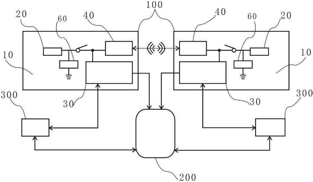
[0028] Such as Figure 1-7 As shown, the present embodiment also provides a monitoring system for place-name signs, including a smart place-name sign 100 and a server 200. The smart place-name sign 100 is suitable for house signs, building signs, street signs, alley signs, and for representing mountains, rivers, Place name signs of lakes, islands, platforms, ports, stations, fields and administrative areas.
[0029] The intelligent place name signage 100 includes a signage body 10, a power supply module 20 and a monitoring function module 30 and a WIFI module 40 arranged on the signage body 10, the power supply module 20 is electrically connected with the monitoring function module 30 and the WIFI module 40, and through the The power supply module 20 provides power support to the monitoring function module 30 and the WIFI module 40 respectively. Preferably, the pow...
PUM
 Abstract
Description
Claims
Application Information