
Electrical connector applied to ventilator

A technology of electrical connectors and ventilating fans, which is applied in the direction of connection, parts of connection devices, protective grounding/shielding devices of connection parts, etc., which can solve the problems of cumbersome positioning and installation, cumbersome wire connection, etc., to simplify the installation method and simplify the product structure Effect

Inactive Publication Date: 2016-07-27
SHANGHAI HOPPY ELECTRONICS ELECTRIC APPLIANCE +2
View PDF6 Cites 0 Cited by
  • Summary
  • Abstract
  • Description
  • Claims
  • Application Information

AI Technical Summary

Problems solved by technology

Ventilation fan products on the market are made by connecting scattered parts around the fan blades through wires. This design and arrangement method has many disadvantages, for example: the wire connection between parts is cumbersome. After the connection is completed, the When the parts are positioned, because they are involved with each other, the positioning and installation are also very cumbersome

Method used


Image

  • Electrical connector applied to ventilator
  • Electrical connector applied to ventilator
  • Electrical connector applied to ventilator

Examples


Embodiment Construction

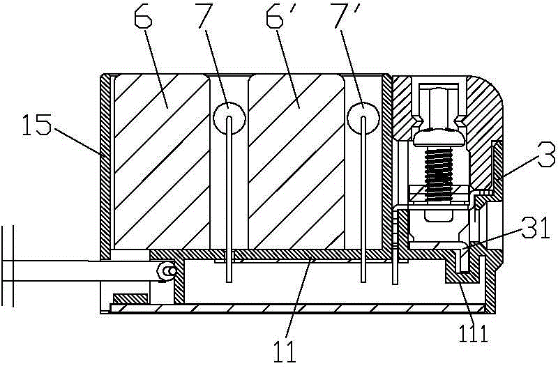
[0015] see Figure 1 to Figure 4 , an electrical connector for a ventilating fan of the present invention, which includes an insulating base 1, which is a shell with an upper opening, and a transverse partition 13 is set in it to form a power supply side chamber and a load arranged in front and back of the internal cavity. The side chambers, wherein the power supply side chambers are also provided with a number of longitudinal partitions 12 in parallel and spaced apart to form four parallel and independent first to fourth compartments a to d, corresponding to the four compartments, the insulating base of the power supply side chamber The front end surface 14 of the seat 1 is provided with four through holes; the rear end surface 15 of the insulating base 1 is provided with through holes for the wires to pass through; slot 111;

[0016] The insulating upper cover 2 is fastened on the power supply side chamber of the insulating base 1, corresponding to the four compartments a t...


PUM


Abstract

The invention provides an electrical connector applied to a ventilator. The electrical connector comprises an insulation base which is a casing body with an upper opening, an insulation cover which is buckled on a power supply side chamber of the insulation base, an insulation bottom cover which is buckled on the bottom of the insulation base, four wire clamping frames, corresponding wiring screws, four conductive terminals which are L-shaped, first and second capacitors which are arranged in a load side chamber of the insulation base with spacing, first and second resistors which are arranged before first and second capacitors in the load side chamber of the insulation base with spacing, and first, second, third and fourth conductive sheets which are respectively connected with three phase lines and grounding lines of first and second capacitors, first and second resistors, four conductive terminals and a ventilator motor connector. Transverse clapboards are arranged in the insulation base, and the power supply side chamber and the load side chamber are arranged in the internal cavity back and forth. First, second, third and fourth compartments are parallelly arranged in the power supply side chamber with spacing. Four wire clamping frames and corresponding wiring screws are respectively arranged in four corresponding compartments of the power supply side chamber of the insulation base. The upper parts of four conductive terminals are inserted into four wire clamping frame, and the lower parts cross a bottom plate. Two pins of the capacitors and the resistors respectively cross the bottom plate.

Description

technical field [0001] The invention relates to an electrical connector, in particular to an electrical connector for a ventilation fan. Background technique [0002] Ventilation fans are usually small in size, leaving little space except for the motor blades. How to reliably and reasonably arrange the components of the starting circuit and the normal operation power supply circuit system in a limited space has become a subject of ventilation fan design. Ventilation fan products on the market are made by connecting scattered parts around the fan blades through wires. This design and arrangement method has many disadvantages, for example: the wire connection between parts is cumbersome. After the connection is completed, the When the parts are positioned, because they are involved with each other, the positioning and installation are also very cumbersome. Simplification, miniaturization and modularization are inevitable trends. Contents of the invention [0003] The purp...

Claims


Application Information

Patent Timeline
Patent Type & Authority Applications(China)
IPC IPC(8): H01R31/06H01R13/02H01R13/502H01R13/648H01R13/66
Inventor 施冉
Owner SHANGHAI HOPPY ELECTRONICS ELECTRIC APPLIANCE
Learn More