Instantaneous frequency measuring method and system

A technology of instantaneous frequency and measurement system, applied in the field of microwave photonics, can solve the problems of large measurement error, mutual exclusion of measurement range and measurement accuracy, difficulty in meeting the requirements of measurement range and measurement accuracy, etc., to achieve the effect of simplifying the structure

Active Publication Date: 2016-07-27
BEIJING UNIV OF POSTS & TELECOMM
View PDF4 Cites 15 Cited by
  • Summary
  • Abstract
  • Description
  • Claims
  • Application Information

AI Technical Summary

Benefits of technology

This patented technology provides a way to measure frequencies accurately without requiring any filters or complicated equipment that affects how much light travels during transmission. It uses both types of lights with identically-polarized beams splitting them up into multiple paths before being sent separately over separate devices like sensors. By measuring these waves twice they get their amplitudes proportional to each other's difference between those on opposite sides. These measurements help determine if the transmitted electromagnetic wave has been properly modified based upon its characteristics such as time delay (time) varying due to factors like temperature).

Problems solved by technology

This patents describes various technical techniques related to improving the performance of high speed electronically controlled nanometer wave technology (HCNW). These include reducing noise interference during measurements, increasing sensitivity at low temperatures, enhancing immunity against electromagnetism while also ensuring accurate results when analyzing small microscopic waves or very weakly absorbing materials such as plasma membranes.

Method used


Image

  • Instantaneous frequency measuring method and system
  • Instantaneous frequency measuring method and system
  • Instantaneous frequency measuring method and system

Examples


Embodiment Construction

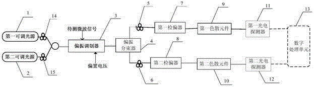
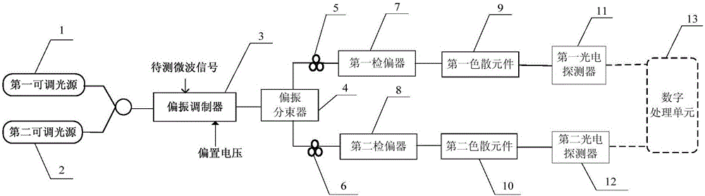
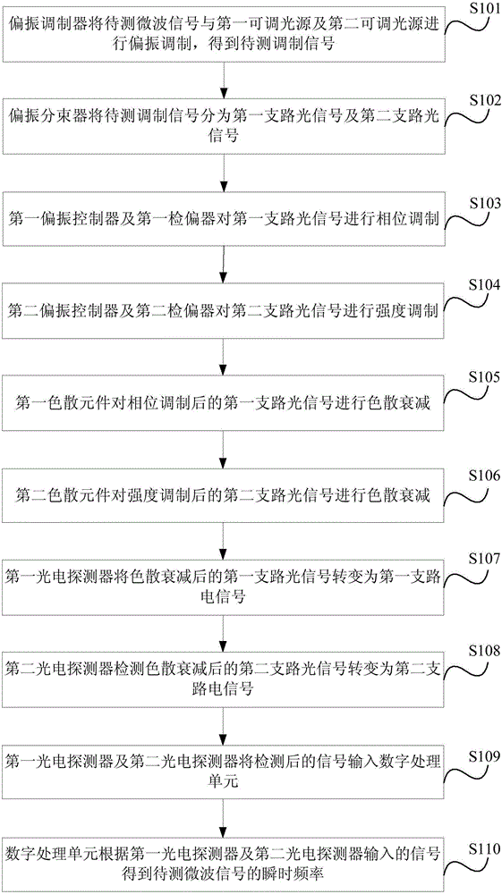
[0054] The following will clearly and completely describe the technical solutions in the embodiments of the present invention with reference to the accompanying drawings in the embodiments of the present invention. Obviously, the described embodiments are only some, not all, embodiments of the present invention. Based on the embodiments of the present invention, all other embodiments obtained by persons of ordinary skill in the art without making creative efforts belong to the protection scope of the present invention. The terms "first", "second", "third", "fourth", etc. (if any) in the description and claims of the present invention and the above drawings are used to distinguish similar objects and not necessarily Describe a particular order or sequence. It is to be understood that the data so used are interchangeable under appropriate circumstances such that the embodiments of the invention described herein can be practiced in sequences other than those illustrated or descri...


PUM


Abstract

The invention provides an instantaneous frequency measuring method and system. The method includes that a polarization modulator performs polarization modulation on to-be-detected microwave signals and a first adjustable light source as well as a second adjustable light source; a polarization beam splitter divides the to-be-detected microwave signals to first branch optical signals and second branch optical signals; a first polarization controller and a first analyzer perform phase modulation on the first branch optical signals; a second polarization controller and a second analyzer performs intensity modulation on the second branch optical signals. A dispersion element is utilized for performing dispersion attenuation on the two branch optical signals. A first photoelectric detector converts the first branch optical signals subjected to dispersion attenuation to first branch electric signals. A second photoelectric detector converts the second branch optical signals subjected to dispersion attenuation to second branch electric signals. A digital processing unit obtains the instantaneous frequency of the to-be-detected microwave signals according to the input signals of the photoelectric detectors. The method and system provided by the invention can meet requirements for measurement range and measurement precision in instantaneous frequency measurement.

Description


Claims


Application Information

Patent Timeline
Owner BEIJING UNIV OF POSTS & TELECOMM
Why Eureka
Try Eureka