Novel gas flow velocity and flow measurement system
A gas velocity and flow measurement technology, applied in fluid velocity measurement, velocity/acceleration/impact measurement, measurement devices, etc., can solve the problems of reducing measurement accuracy, affecting gas flow velocity, etc., and achieve the effect of low power demand.
- Summary
- Abstract
- Description
- Claims
- Application Information
AI Technical Summary
Problems solved by technology
Method used
Image
Examples
example 1
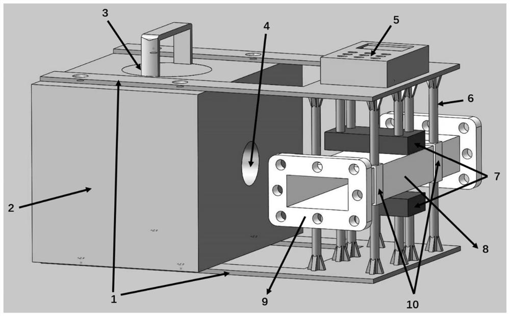
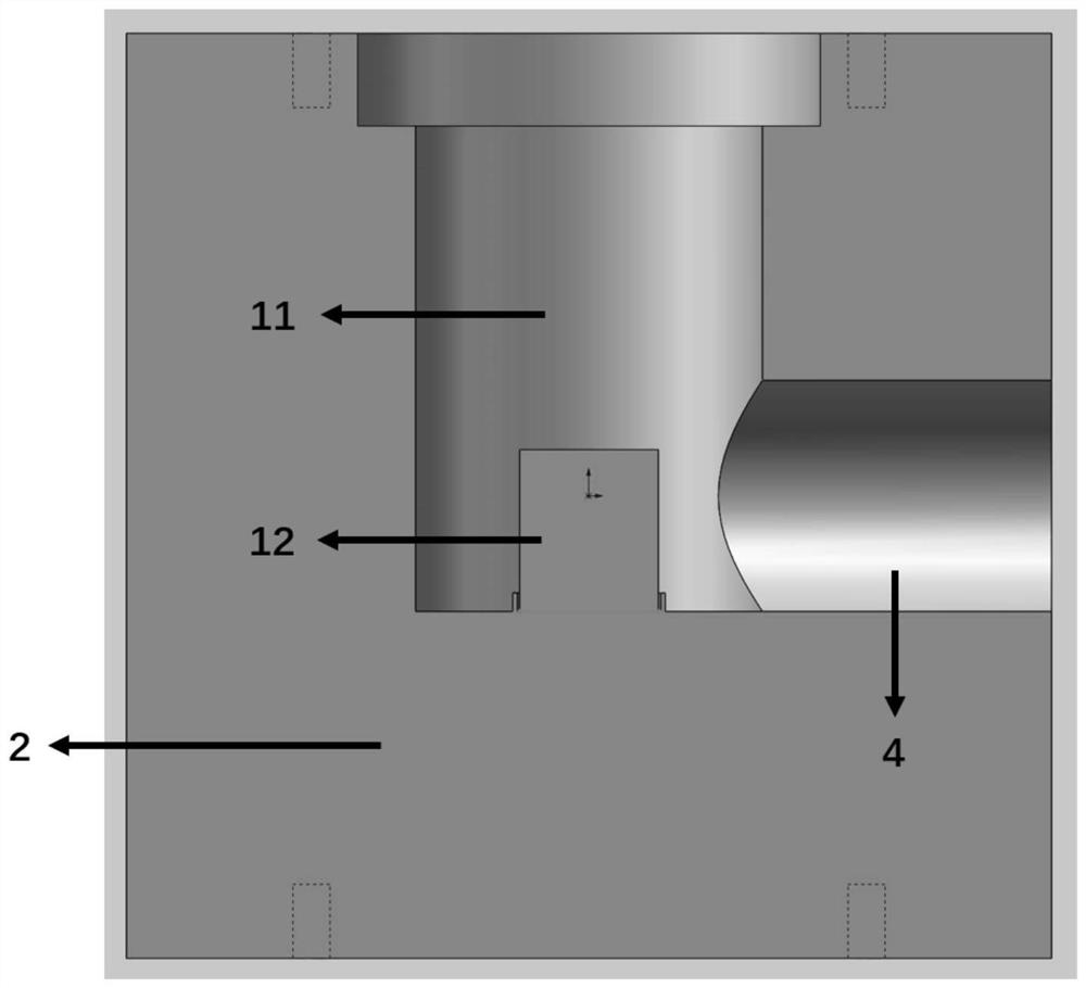
[0026] A new type of gas velocity flow measurement system, the overall structure is as follows figure 2 shown. figure 2 Shielding body 2, shielding cover 3, collimation hole 4 and image 3 Inner chamber 11, cylindrical 60 The Co radiation source 12 constitutes an ionizing radiation source and its collimation shielding module. The shielding upper cover 3 is placed on the top of the shielding body 2 to prevent the radiation in the inner chamber 11 from leaking out, such as figure 2 As shown, when working, the shielding upper cover 3 can be opened and the radioactive source is placed in the limit groove at the bottom of the inner chamber 11, as image 3 shown. figure 2 The gas guide tube 8, the flange assembly 9, the RuFeB magnet 7 and Figure 5 The electrodes 15 in constitute the measurement module. The gas guide tube 8 is fixed in the middle of the upper and lower parallel fixed components 1 through the support frame 10 and the support column 6 and kept horizontal. Th...
example 2
[0029] A new type of gas velocity flow measurement system, the structure is basically the same as that described in Example 1, the difference is that the ionizing radiation source used is an X-ray tube 13, and the X-ray tube can be directly embedded in the shielding body 2 of the device and kept The X-ray window 14 is aligned with the collimation hole 4, such as Figure 4 shown. X-rays are emitted from the X-ray window 14 and collimated to the side of the gas guide tube 8 through the collimation hole 4 . By adjusting the X-ray tube to output different energies, X-rays with different intensities can be adapted to different measurement gases.
example 3
[0031] A new type of gas flow rate and flow measurement system, the structure is basically the same as that described in Example 1, the difference is that the magnetic field generating device that provides the magnetic field is an electromagnet, by adjusting the excitation voltage, the size of the magnetic field can be changed to change the Hall voltage sizes to meet different measurement ranges.
[0032] The present invention is realized according to following measuring principle:
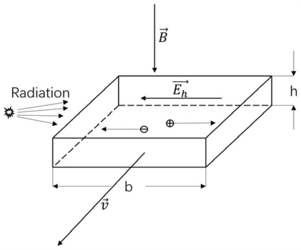
[0033] Such as figure 1 , the magnetic induction intensity of two magnets in the vertical direction of the gas guide tube is magnetic field. When the gas medium is at a velocity When flowing through a gas duct with a cross-sectional width of b and a height of h, due to the ionization of gas atoms under the irradiation of ionizing radiation, electrons and positive ions are respectively subjected to the Lorentz force, and the force is:
[0034]
[0035] In the formula is the velocity of m...
PUM
 Abstract
Description
Claims
Application Information
 - R&D
- Intellectual Property
- Life Sciences
- Materials
- Tech Scout
- Unparalleled Data Quality
- Higher Quality Content
- 60% Fewer Hallucinations
Browse by: Latest US Patents, China's latest patents, Technical Efficacy Thesaurus, Application Domain, Technology Topic, Popular Technical Reports.
© 2025 PatSnap. All rights reserved.Legal|Privacy policy|Modern Slavery Act Transparency Statement|Sitemap|About US| Contact US: help@patsnap.com


