
Self-vibrating type material clearing tube device for housing stretching-out section of material-pushing centrifugal machine

A centrifuge and cleaning pipe technology, applied in the field of centrifuges, can solve problems such as material blockage in the discharge pipe and centrifuge failure, and achieve the effects of simple structure, guaranteed safety, and low overall cost

Active Publication Date: 2016-08-03
ZHEJIANG QINGJI CENTRIFUGE MFG
View PDF10 Cites 0 Cited by
  • Summary
  • Abstract
  • Description
  • Claims
  • Application Information

AI Technical Summary

Problems solved by technology

[0003] The purpose of the present invention is to solve the problem that when the existing two-stage pusher centrifuge uses a closed circular tube collection tank, especially in the treatment of materials with a relatively high moisture content, the discharge pipe is prone to blockage, thus causing the centrifuge To solve the problem of failure, provide a self-shock cleaning pipe device with a reasonable structural design and no need for additional power.

Method used


Image

  • Self-vibrating type material clearing tube device for housing stretching-out section of material-pushing centrifugal machine
  • Self-vibrating type material clearing tube device for housing stretching-out section of material-pushing centrifugal machine
  • Self-vibrating type material clearing tube device for housing stretching-out section of material-pushing centrifugal machine

Examples


Embodiment Construction

[0020] The technical solutions of the present invention will be further specifically described below through the embodiments and in conjunction with the accompanying drawings.

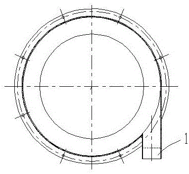
[0021] see figure 1 , The present embodiment is a self-vibration cleaning pipe device for the extension section of the pusher centrifuge casing, which is designed on the extension section of the casing when the double-stage pusher centrifuge uses a closed circular tube collection tank.

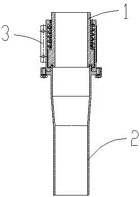
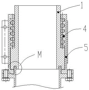
[0022] Install the discharge pipe 2 through the intermediate transition body on the extension section 1 of the casing, such as figure 2 As shown, the inner hole of the discharge pipe 2 has a section of taper, that is, the discharge pipe 2 can be divided into three sections according to the inner hole: the first section is a straight pipe section whose aperture is larger than the inner hole of the casing extension section 1, and the second section The first section is the taper section connected with the straight pipe...


PUM


Abstract

The invention relates to a self-vibrating type material clearing tube device for a housing stretching-out section of a material-pushing centrifugal machine, and the self-vibrating type material clearing tube device solves the problem that failure of the centrifugal machine is caused due to the fact that a discharge tube is liable to block when a current double-stage material-pushing centrifugal machine uses a closed type circular tube collecting slot and is especially used for treating materials with relatively high moisture content. The self-vibrating type material clearing tube device is characterized in that the discharge tube with a tapered section in an inner hole is connected on the housing stretching-out section through a transitional body; elastic expansion amount is kept between the discharge tube and the housing stretching-out section, and an elastic body is arranged; impact force generated when the materials flow out of a collecting slot is utilized, and when the impact force acts on the taper section of the discharge tube, the discharge tube downwards moves within an elastic expansion amount range, and therefore, the materials are intermittently discharged, the elastic body is continuously compressed and rebounded, and vibration collision is generated between the housing stretching-out section and the transitional body. According to the self-vibrating type material clearing tube device, self-vibrating can be realized without additional power, material accumulation is avoided, and the safety of the overall equipment is guaranteed; and the structure is simple, and the comprehensive cost is low.

Description

technical field [0001] The invention relates to the technical field of centrifuges, in particular to a self-vibration cleaning pipe device for the extension section of the casing of a pusher centrifuge. Background technique [0002] The discharge anti-blocking device in industrial products has various designs according to the characteristics of the product itself. These designs are basically self-contained independent power source. For example, the patent announcement number is CN204685309U, a centrifuge anti-clogging discharge device, including a motor, a rotating shaft, a driven shaft, a conveyor belt and a turntable, the motor output shaft is keyed to the rotating shaft, and the rotating shaft is connected to the driven shaft through a conveyor belt. Both ends of the rotating shaft and both ends of the driven shaft are rotatably connected to the inner wall of the discharge pipe, the turntable is keyed to the rotating shaft, there is a pushing plate on the turntable, and ...

Claims


Application Information

Patent Timeline
Patent Type & Authority Applications(China)
IPC IPC(8): B04B11/04
CPCB04B11/04
Inventor 王刘波陶渊卿
Owner ZHEJIANG QINGJI CENTRIFUGE MFG
Learn More