
A rigidity-adjustable engine mount

An engine mount and adjustable technology, which is applied in the mechanical field to achieve the effects of cost reduction, force buffering, and shortening the development cycle

Active Publication Date: 2019-02-12
ZHEJIANG GEELY AUTOMOBILE RES INST CO LTD +1
View PDF11 Cites 0 Cited by
  • Summary
  • Abstract
  • Description
  • Claims
  • Application Information

AI Technical Summary

Problems solved by technology

[0006] The purpose of the present invention is to solve the above-mentioned problems in the existing technology, and propose an engine mount with adjustable stiffness. The technical problem to be solved by the present invention is: how to realize a wide range of adjustable stiffness of the engine mount, reduce waste, Reduce costs and improve applicability

Method used


Image

  • A rigidity-adjustable engine mount
  • A rigidity-adjustable engine mount
  • A rigidity-adjustable engine mount

Examples


Embodiment Construction

[0034] The following are specific embodiments of the present invention and in conjunction with the accompanying drawings, further describe the technical solution of the present invention, but the present invention is not limited to these embodiments.

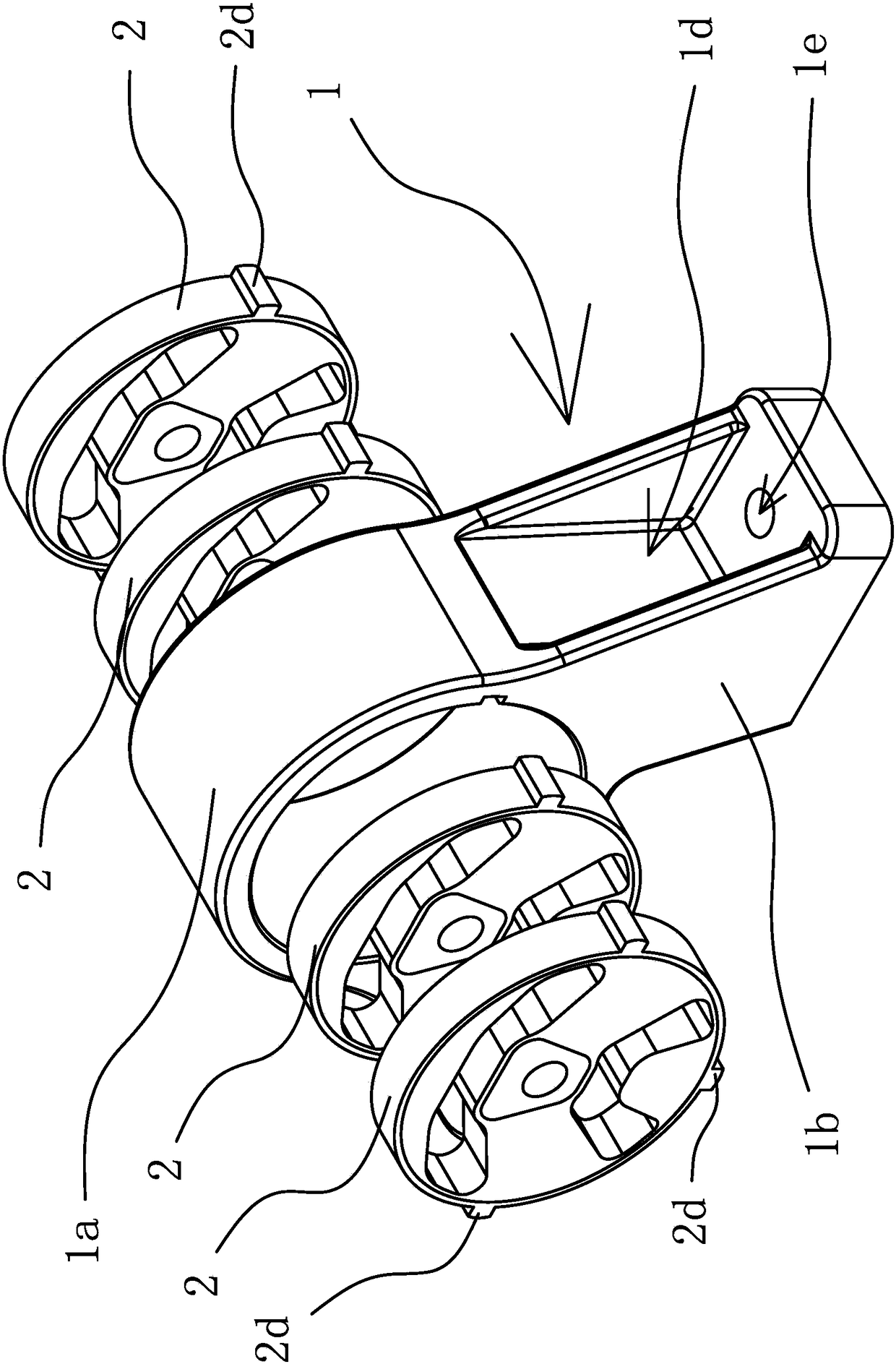
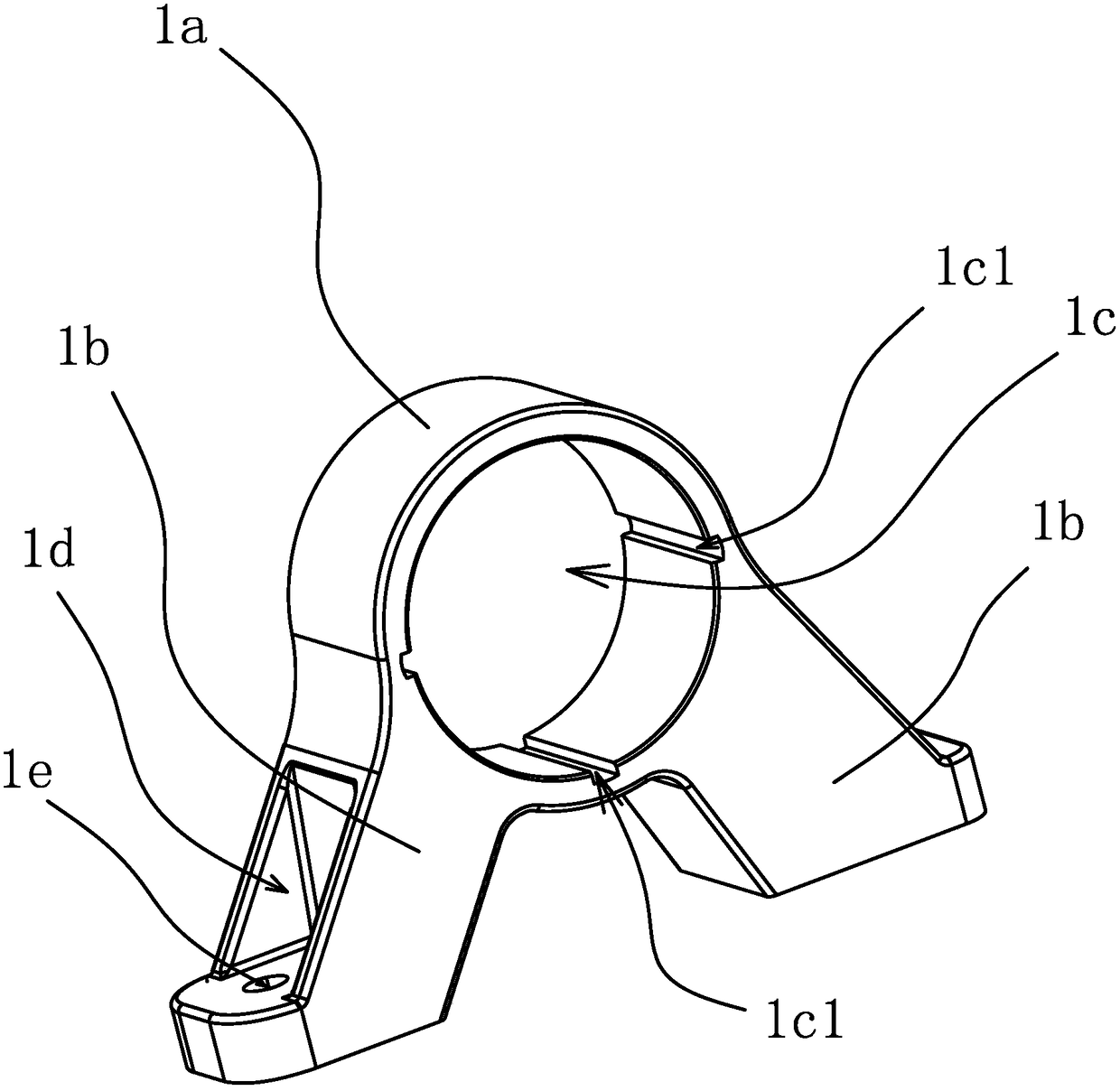
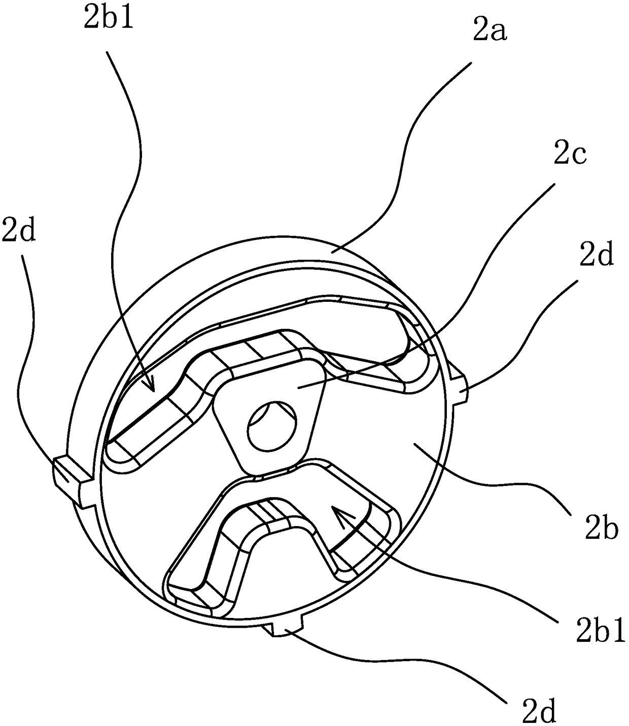
[0035] Such as Figure 1-4 As shown, the engine mount with adjustable stiffness includes a connection bracket 1 and a suspension main spring 2. The connection bracket 1 has an installation cavity 1c that runs through both ends of the connection bracket 1. The suspension main spring 2 and the installation cavity 1c are both in the shape of The columnar, suspended main spring 2 can be arranged in the installation cavity 1c and tightly fitted with the inner wall of the installation cavity 1c.

[0036] Specifically, as figure 2 As shown, the connecting bracket 1 includes a cylindrical mounting part 1a and two legs 1b, the mounting cavity 1c is the inner cavity of the cylindrical mounting part 1a, the two legs 1b are relatively inc...


PUM


Abstract

The invention provides an engine suspension with the adjustable rigidity and belongs to the technical field of machines. The engine suspension solves the problems that an existing engine suspension is limited in adjusting range, high in cost and poor in adaptability. The engine suspension with the adjustable rigidity comprises a connecting support and main suspension springs. The connecting support is provided with an installation cavity penetrating the two end faces of the connecting support. The two end faces of each main suspension spring are smooth planes. The main suspension springs can be arranged in the installation cavity and connected with the inner wall of the installation cavity in a tight fit manner. The axial depth of the installation cavity is larger than the thickness of the main suspension springs. By the adoption of the engine suspension, the rigidity of the suspension can be directly changed directly through the increase and reduction of the number of the main suspension springs, the rigidity is adjusted conveniently and rapidly, the rigidity adjusting range is wide, the rigidity adjusting accuracy is high, the adaptability to different vehicle models and different engines is good, manpower and material resources can be saved to a great extent, waste and cost are reduced, and a development period is shortened.

Description

technical field [0001] The invention belongs to the technical field of machinery and relates to an engine mount, in particular to an engine mount with adjustable stiffness. Background technique [0002] With the development of science and technology and the improvement of people's living standards, the comfort of cars has attracted more and more attention. The comfort of the car is greatly affected by the NVH performance. Therefore, the major OEMs have taken the NVH performance of the car as an important design index. Engine mounts can effectively attenuate the transmission of engine vibration to the body / frame, and play an increasingly important role in automotive NVH design. The suspension rubber main spring is used to connect the car frame and the engine support. In order to enhance the comfort of the car, reduce the transmission of engine vibration to the body and at the same time provide the necessary support for the engine, so the rigidity of the engine mount high ex...

Claims


Application Information

Patent Timeline
Patent Type & Authority Patents(China)
IPC IPC(8): B60K5/12F16F1/38
CPCB60K5/1275F16F1/38F16F1/3863
Inventor 马艳恒陆宏飞
Owner ZHEJIANG GEELY AUTOMOBILE RES INST CO LTD
Learn More