A high-speed EMU drainage device

A technology for high-speed EMU and drainage device, which is applied in the directions of transportation and packaging, railway car body parts, railway transportation, etc., can solve the problems such as difficult to achieve lightweight car body, smaller effective volume of drainage cavity, and inability to effectively store wastewater, etc. To achieve the effect of reducing the frequency of cleaning and maintenance, achieving light weight and reducing the overall height

Active Publication Date: 2018-08-24
CRRC QINGDAO SIFANG CO LTD
View PDF5 Cites 0 Cited by
  • Summary
  • Abstract
  • Description
  • Claims
  • Application Information

AI Technical Summary

Problems solved by technology

[0002] EMUs, urban rail and subway trains generally have washrooms, and the waste water in the washrooms is directly discharged out of the train through the drainage device installed under the train, such as figure 1 As shown, the interior of the drainage device is divided into a drainage chamber and a water inlet chamber, and the penetration and drainage are realized through the siphon tube. The drainage pipes are directly installed in the drainage chamber to discharge the waste water from the bottom of the drainage chamber. However, due to space constraints, the drainage The device is generally small in size, and the drainage pipeline is also placed, which further leads to the reduction of the effective volume of the drainage cavity. Therefore, the drainage device generally cannot effectively store waste water and must be discharged at any time. In order to ensure air tightness, the drainage device generally only has one drain. It is not easy to maintain when the pipe outlet is clogged, and it is not easy to achieve the purpose of reducing the weight of the car body

Method used


Image

  • A high-speed EMU drainage device
  • A high-speed EMU drainage device

Examples


Embodiment Construction

[0017] The present invention will be further described in detail below in conjunction with the accompanying drawings and specific embodiments.

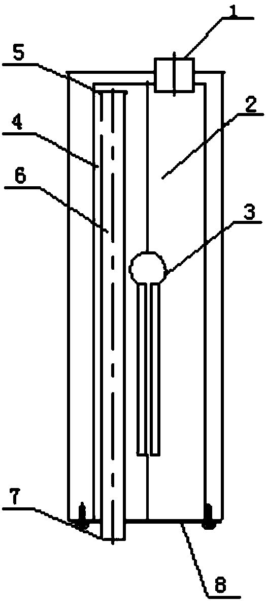
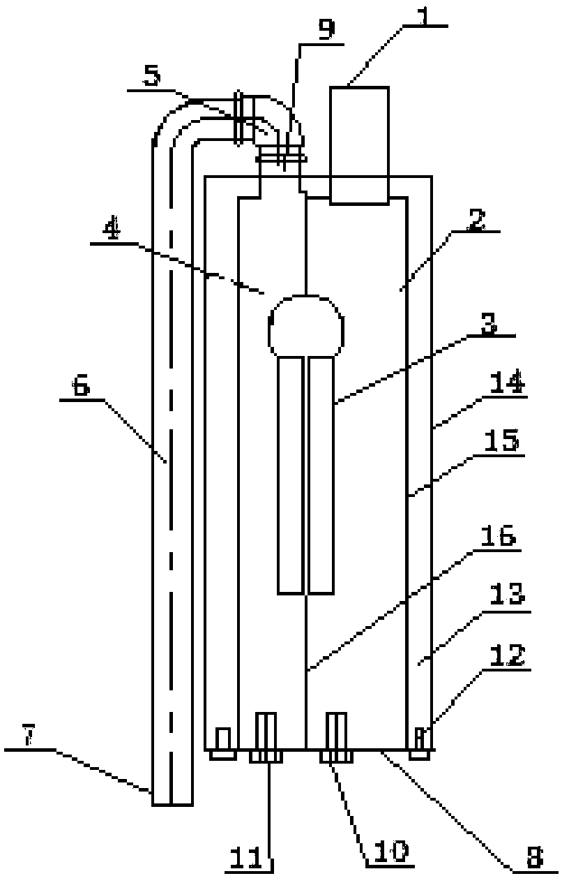
[0018] The present invention provides a high-speed motor car drainage device, including a water collection container and a drainage pipeline 6. The water collection container includes a casing 14 and a cavity 15 inside the casing 14. The inside of the cavity 15 is divided into a drainage cavity 4 and a drainage cavity 4 by a partition 16. The water inlet chamber 2, the siphon tube 3 installed on the partition 16 connects the drainage chamber 4 and the water inlet chamber 2, the top of the water inlet chamber 2 is connected to the water inlet pipe 1, and the top of the drainage chamber 4 is connected to the drainage pipeline through the water inlet pipe interface 9 The drain pipe inlet 5 of 6, the drain pipe 6 is located outside the water collection container, the drain pipe outlet 7 at the end of the drain pipe 6 is located below the w...


PUM


Abstract

The invention provides a drainage device for a high-speed motor train unit. The drainage device comprises a water collecting container and a drainage pipeline. The water collecting container comprises a shell and a cavity in the shell. The interior of the cavity is divided into a drainage cavity and a water inflow cavity through a partition plate. The drainage cavity and the water inflow cavity communicate with each other through a siphon installed on the partition plate. The top of the water inflow cavity is connected with a water inflow pipe. The top of the drainage cavity communicates with a drainage pipe inlet of the drainage pipeline through a water inflow pipe joint. The drainage pipeline is located outside the water collecting container. A drainage pipe outlet in the tail end of the drainage pipeline is located below the horizontal plane of the bottom of the water collecting container. By the adoption of the drainage device for the high-speed motor train unit, the structure is simple, washing wastewater can be effectively stored, and a low weight purpose can be achieved.

Description

technical field [0001] The invention relates to a drainage device, in particular to a drainage device suitable for high-speed EMUs. Background technique [0002] EMUs, urban rail and subway trains generally have washrooms, and the waste water in the washrooms is directly discharged out of the train through the drainage device installed under the train, such as figure 1 As shown, the interior of the drainage device is divided into a drainage chamber and a water inlet chamber, and the penetration and drainage are realized through the siphon tube. The drainage pipes are directly installed in the drainage chamber to discharge the waste water from the bottom of the drainage chamber. However, due to space constraints, the drainage The device is generally small in size, and the drainage pipeline is also placed, which further leads to the reduction of the effective volume of the drainage cavity. Therefore, the drainage device generally cannot effectively store waste water and must b...

Claims


Application Information

Patent Timeline
Patent Type & Authority Patents(China)
IPC IPC(8): B61D35/00
CPCB61D35/007Y02T30/00
Inventor 李丰贾树峰李冬冬邢丽张林楠陶桂东盖增杰刘慧峰杨旭升
Owner CRRC QINGDAO SIFANG CO LTD
Why Eureka
Try Eureka