An optical fiber screening and rewinding anti-whiplash device

An anti-whiplash and optical fiber technology, which is applied in the field of optical fiber manufacturing, can solve the problems of optical fiber quality impact, optical fiber waste, increased manpower and equipment costs, etc., and achieve the effect of reasonable design, quality assurance, and elimination of optical fiber

Inactive Publication Date: 2018-08-03
JIANGSU HENGTONG OPTICAL FIBER TECH
View PDF16 Cites 2 Cited by
  • Summary
  • Abstract
  • Description
  • Claims
  • Application Information

AI Technical Summary

Problems solved by technology

But at the moment of fiber breaking, the motor at the take-up end is still running at high speed. At this time, the take-up fiber optic reel is running at high speed, and the fiber continues to wind around the fiber reel. At this time, the broken end of the fiber is constantly whipping the fiber to take up the fiber at high speed. The optical fiber on the surface of the disk has a serious impact on the quality of the optical fiber
[0003] In order to ensure the quality of the optical fiber, it is necessary to cut off the optical fiber on the surface of the optical fiber take-up reel. This process leads to the waste of optical fiber on the one hand, and increases the cost of manpower and equipment on the other hand.
[0004] At present, in order to reduce the impact of whipping on screening rewinders, a protective cover is generally installed at the take-up end to limit the swinging range of the broken end of the optical fiber to a certain extent and reduce the whipping force, but this method cannot fundamentally prevent to whip

Method used


Image

  • An optical fiber screening and rewinding anti-whiplash device
  • An optical fiber screening and rewinding anti-whiplash device

Examples


Embodiment

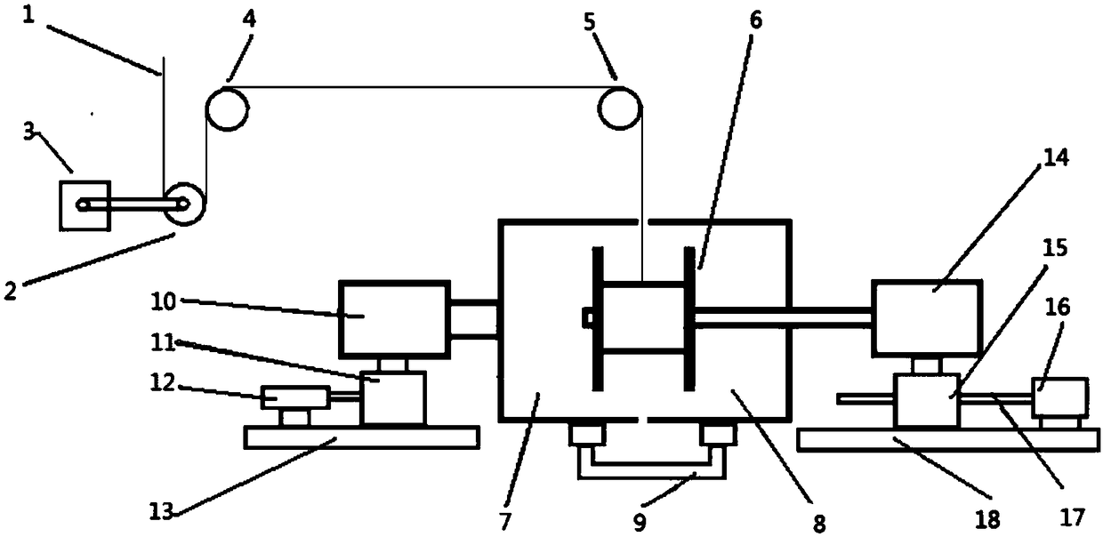
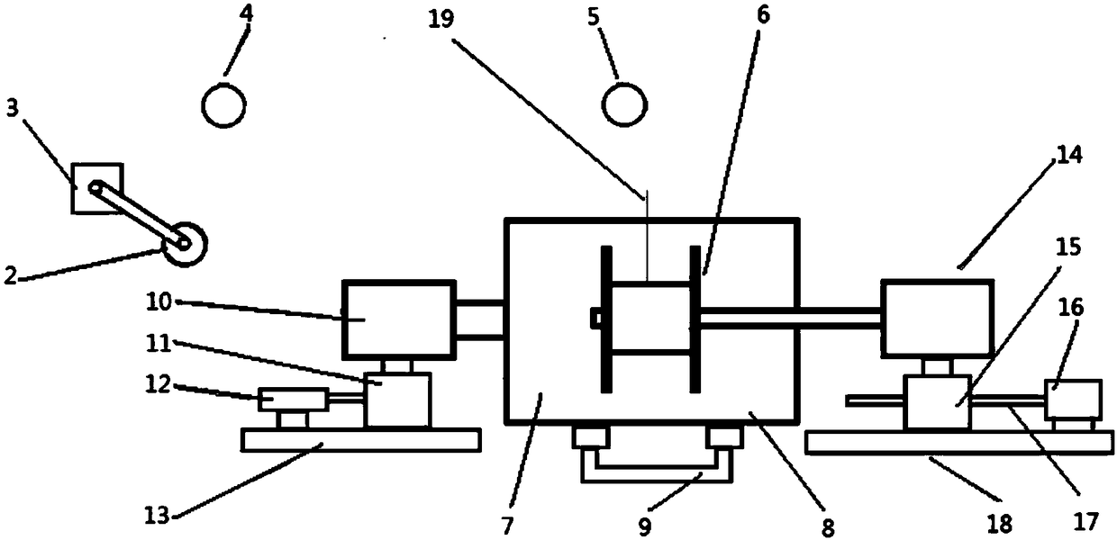
[0030] refer to figure 1 As shown, this embodiment discloses an optical fiber screening and rewinding anti-whiplash device. The specific structure of the device is as follows:

[0031] The optical fiber 1 enters the optical fiber screening and rewinding device from the end of the dancing wheel 2, the above-mentioned dancing wheel 2 is supported by a support rod, one end of the above-mentioned supporting rod is connected to the above-mentioned dancing wheel 2, the other end of the above-mentioned supporting rod is fixed, and the above-mentioned supporting rod The other end is provided with dancing wheel sensor 3, in fact, above-mentioned dancing wheel 2 is not a fixed state, when above-mentioned dancing wheel 2 has optical fiber to pass through (optical fiber 1 gives it an upward lifting force) when being in horizontal position, above-mentioned dancing wheel 2 When no optical fiber passes through, the position drops due to its own gravity.

[0032] The optical fiber 1 enters t...


PUM


Abstract

The invention discloses an optical fiber screening, rewinding and whip preventing device. The device comprises a dancing wheel, a lead, a wire arranging wheel and an optical fiber wire collecting disc; the optical fiber wire collecting disc is coated with a first protective cover and a second protective cover; optical fibers enter the optical fiber wire collecting disc from a gap between the first protective cover and the second protective cover; a first motor drives the first protective cover to rotate; meanwhile, a transmission device drives the second protective cover to synchronously rotate; a second motor drives the optical fiber wire collecting disc to rotate; and when the optical fibers are broken, an air pressure rod pushes a first base to move on a first guide rail, and the first protective cover is pushed to the second protective cover, so that the first protective cover and the second protective cover tightly clamp the broken ends of the optical fibers. When the optical fibers are broken in screening and rewinding caused by the strength problem of the optical fibers or the equipment problem, the broken ends of the optical fibers can be clamped through the device to prevent from continuously whipping the optical fibers on the surface of the optical fiber wire collecting disc in a high-speed state so as to prevent influence on the quality of the optical fibers.

Description

technical field [0001] The invention relates to the field of optical fiber manufacturing, in particular to an optical fiber screening and rewinding anti-whiplash device. Background technique [0002] In the optical fiber manufacturing process, it involves the screening and rewinding process. During the fiber screening and rewinding process, under normal circumstances, when the screening and rewinding ends, the motor at the take-up end stops running, and the optical fiber on the take-up fiber reel and the fiber on the pay-off end reel are still in a state of complete connection. When there is a problem with the fiber strength or the equipment itself that causes fiber breakage during screening and rewinding, the motor at the take-up end will gradually stop from high-speed operation for about 5 seconds. But at the moment of fiber breaking, the motor at the take-up end is still running at high speed. At this time, the take-up fiber optic reel is running at high speed, and the f...

Claims


Application Information

Patent Timeline
Patent Type & Authority Patents(China)
IPC IPC(8): B65H63/036
CPCB65H63/036
Inventor 张良陈伟袁健贺作为戚仁宝曹少波
Owner JIANGSU HENGTONG OPTICAL FIBER TECH
Why Eureka
Try Eureka