Lifting platform for electric power overhauling

A technology of lifting platform and electric maintenance, applied in the direction of lifting device, etc., to achieve the effect of uniform force

Inactive Publication Date: 2016-08-03
STATE GRID SHANDONG ELECTRIC POWER CO LONGKOU POWER SUPPLY CO
View PDF9 Cites 22 Cited by
  • Summary
  • Abstract
  • Description
  • Claims
  • Application Information

AI Technical Summary

Problems solved by technology

[0002] Existing lifting platforms for electric power maintenance usually have a relatively simple structure, and are lifted by means of steel cable hoisting. Since

Method used


Image

  • Lifting platform for electric power overhauling
  • Lifting platform for electric power overhauling
  • Lifting platform for electric power overhauling

Examples


Embodiment 1

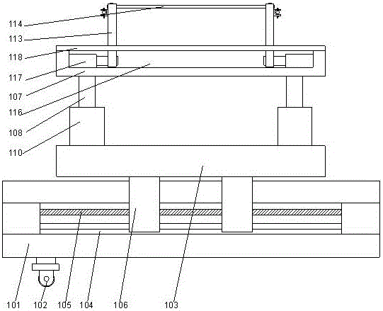
[0024] Such as figure 1 , 2 As shown, the power maintenance lifting platform includes a base 101 and a universal wheel 102 arranged below the base 101, a horizontal moving platform 103 is arranged above the base 101, and the side walls on both sides of the base 101 There are chute 104 respectively arranged on it, and lead screw 105 is arranged in described chute 104, and lead screw base is set respectively on both sides of described chute 104, and the inside of described lead screw base is provided with for driving The motor of the lead screw 105 is provided with sliders 106 on both sides of the horizontal moving platform 103, and the slider 106 is sleeved on the lead screw 105 and can move along the lead screw 105. 105 moves in the axial direction, a vertical moving platform 107 is arranged above the horizontal moving platform 103, and four lifting devices 108 are arranged between the vertical moving platform 107 and the horizontal moving platform 103, and the The eleva...

Embodiment 2

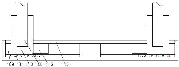
[0028] This embodiment is based on Embodiment 1. In this embodiment, in order to enable the sliding base hydraulic cylinder to be located inside the horizontal moving platform and avoid its damage, preferably, an end cover 115 is provided on the horizontal moving platform 103 , the end cover 115 covers above the clamping slot 109 , and the end cover 115 is provided with through slots corresponding to the positions of the clamping slot 109 . By adopting the end cover provided with the through groove, the sliding base can be moved along the length direction of the through groove, thereby preventing the hydraulic cylinder of the sliding base from being damaged when the sliding base is subjected to a force perpendicular to the axial direction of the hydraulic cylinder of the sliding base.

Embodiment 3

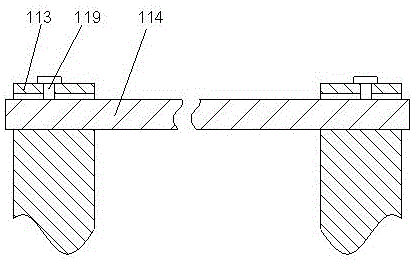
[0030] This embodiment is based on Embodiment 1. In this embodiment, in order to facilitate the movement of the position of the slider, the position of the working area above the vertical moving platform is determined as required. Preferably, the two sides of the vertical moving platform 107 are respectively A stepped groove 116 is provided, the lower end of the sliding rod 113 is located inside the stepped groove 116, and a sliding rod hydraulic cylinder 117 is respectively provided at both ends of the stepped groove 116, and the telescopic rod of the sliding rod hydraulic cylinder 117 is fixedly connected on the lower end surface of the sliding rod 113 .

[0031]Push the lower part of the sliding rod to move along the length of the ladder groove through the hydraulic cylinder of the sliding rod. By adjusting the distance between the two sliding rods, adjust the distance between the armrests on both sides accordingly. It is necessary to determine the size of the working area ...


PUM


Abstract

The invention discloses a lifting platform for electric power overhauling. The lifting platform for electric power overhauling comprises a base and universal wheels which are arranged under the base. A horizontal movement platform is arranged above the base. Sliding grooves are formed in the side walls of the two sides of the base correspondingly. Lead screws are arranged in the sliding grooves. Lead screw bases are arranged on the two sides of each sliding groove correspondingly. Motors used for driving the lead screws are arranged on the inner sides of the lead screw bases. Sliding blocks are arranged on the two sides of the horizontal movement platform correspondingly. The sliding blocks are arranged on the lead screws in a sleeving mode and can move in the axis direction of the lead screws. A vertical movement platform is arranged above the horizontal movement platform. Four lifting devices are arranged between the vertical movement platform and the horizontal movement platform. According to the lifting platform for electric power overhauling, three-direction movement of the lifting platform in the horizontal direction and the vertical direction can be achieved.

Description

technical field [0001] The invention relates to an electric power maintenance lifting platform. Background technique [0002] Existing lifting platforms for electric power maintenance usually have a relatively simple structure, and are lifted by means of steel cable hoisting. Since they can only move in the vertical direction, during use, when construction needs to be carried out at different positions, it is necessary to Adjust it as a whole. Contents of the invention [0003] The purpose of the present invention is to provide an electric maintenance lifting platform, which can improve the problems existing in the prior art, and can realize the three-way movement of the lifting platform in the horizontal direction and the vertical direction. [0004] The present invention is realized through the following technical solutions: [0005] The electric power maintenance lifting platform includes a base and universal wheels arranged under the base, a horizontal moving platfor...

Claims


Application Information

Patent Timeline
IPC IPC(8): B66F11/04
CPCB66F11/04
Inventor 王金鹏山峰张铭昕刘幸媛于业庆唐居诚
Owner STATE GRID SHANDONG ELECTRIC POWER CO LONGKOU POWER SUPPLY CO
Why Eureka
Try Eureka