
Automatically Controlled Computer Host Cooling System

A cooling system and computer technology, applied in computing, instruments, electrical and digital data processing, etc., can solve the problems of computer paralysis, inconvenience in people's life and work, slow running speed, etc., and achieve convenient positioning and fixing, convenient detection, and convenient control. Effect

Active Publication Date: 2019-01-18
黑龙江省诚美盛世知识产权运营有限公司
View PDF6 Cites 0 Cited by
  • Summary
  • Abstract
  • Description
  • Claims
  • Application Information

AI Technical Summary

Problems solved by technology

[0002] Today's computers are self-equipped with cooling fans, but due to frequent daily use and hot weather, the main board in the main box is prone to overheating, causing the computer to be paralyzed, or the running speed is extremely slow, causing inconvenience to people's life and work.

Method used


Image

  • Automatically Controlled Computer Host Cooling System
  • Automatically Controlled Computer Host Cooling System
  • Automatically Controlled Computer Host Cooling System

Examples


Embodiment 1

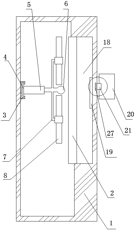
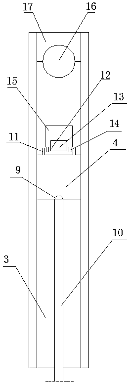
[0029] An automatically controlled cooling system for a mainframe computer, which consists of: a probe 6, a mainframe 1, a mainboard 2, the mainframe 1 is loaded with the mainboard 2, and the left end of the inner surface of the mainframe 1 (the distance from the mainboard is far inner surface) to install the slideway 3, the slider 4 slides on the slideway 3, the slider 4 is connected to the telescopic rod 5, and the top end of the telescopic rod 5 is connected to the probe 6, and the telescopic rod 5 is connected to the probe 6. The inner rod of rod 5 is connected with L-shaped hollow rod 7, and fan 8 is connected on the described L-shaped hollow rod 7, and the outer end of described slide block 4 has arc-shaped groove 9, and described arc-shaped groove 9 is used in conjunction with the push rod 10, the inner end of the slider 4 is connected to the shaft 12 through the shaft sleeve I11, the orientation piece 13 is connected to the shaft 12, the shaft sleeve II14 is connected t...

Embodiment 2

[0031] In the automatically controlled computer mainframe heat dissipation system described in Embodiment 1, thermocouples 19 are placed in the empty groove 18 at the right end of the inner surface of the main board 2 and the main chassis 1, and the thermocouples 19 and the probes 6 are connected to the temperature Sensor, the temperature sensor includes an outer casing 20 , and the outer casing 20 is connected to the right end of the outer surface of the main chassis 1 through an elastic clip 21 .

Embodiment 3

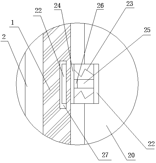
[0033] In the automatic control heat dissipation system for computer mainframes described in Embodiment 2, the elastic clip 21 includes a C-shaped plate 22, the top surface of the C-shaped plate 22 is connected to the spring 23, and the bottom surface of the spring 23 is connected to the pressure plate 24, the pressure plate 24 is arranged in the C-shaped plate 22, the vertical side of the C-shaped plate 22 has a sliding port 25, and the sliding port 25 slides on the fixed block 26, the The fixed block 26 is connected on the pressing plate 24. The right end of the outer surface of the main chassis 1 is provided with an L-shaped slot 27, and the elastic clip 21 is inserted into the L-shaped slot 27.


PUM


Abstract

The invention relates to an automatically controlled computer mainframe cooling system. A mainboard is installed in a mainframe case. A slide rail is installed at the left end of the inner surface of the mainframe case. A slide block slides on the slide rail. A telescopic rod is connected to the slide block. A probe is connected to the top end of the telescopic rod. An L-shaped hollow rod is connected to an inner rod of the telescopic rod. A fan is connected to the L-shaped hollow rod. An arc-shaped groove is formed in the outer end of the slide block and cooperates with a pushing rod in use. The inner end of the slide block is connected with a rotary shaft through a shaft sleeve I. Directional blades are connected to the rotary shaft. A shaft sleeve II is connected to the rotary shaft and connected with a locating clamp rod. The locating clamp rod cooperates with a locating hole in use. The locating hole is formed in the inner end of the slide rail. The inner end of the slide rail is fixedly connected with a stop dog with an arc groove. The automatically controlled computer mainframe cooling system is used for cooling a computer mainframe.

Description

technical field [0001] The invention relates to an automatically controlled cooling system for a computer host. Background technique [0002] Present computers are self-equipped with cooling fans, but due to frequent daily use and hot weather, the main board in the main box is easily paralyzed due to overheating, or the operating speed is extremely slow, which causes inconvenience to people's life and work. Contents of the invention [0003] The purpose of the present invention is to provide an automatically controlled heat dissipation system for a computer mainframe, which uses probes and thermocouples to form a bidirectional temperature detection system, and then automatically turns on the fan to dissipate heat under the control of the temperature sensor. [0004] Above-mentioned purpose realizes by following technical scheme: [0005] An automatically controlled cooling system for a mainframe computer, which consists of: a probe 6, a mainframe 1, a mainboard 2, the mai...

Claims


Application Information

Patent Timeline
Patent Type & Authority Patents(China)
IPC IPC(8): G06F1/20
CPCG06F1/20
Inventor 章广志马春华孙晓霞
Owner 黑龙江省诚美盛世知识产权运营有限公司
Learn More