Mobile terminal, antenna switching method and apparatus for mobile terminal
A mobile terminal and antenna switching technology, which is applied to antenna supports/installation devices, devices that make antennas work in different bands at the same time, antennas, etc., which can solve complex switching algorithms, unreasonable antenna layout, and poor mobile terminal signals. problem, to achieve the effect of solving the complex switching algorithm
- Summary
- Abstract
- Description
- Claims
- Application Information
AI Technical Summary
Problems solved by technology
Method used
Image
Examples
no. 1 example
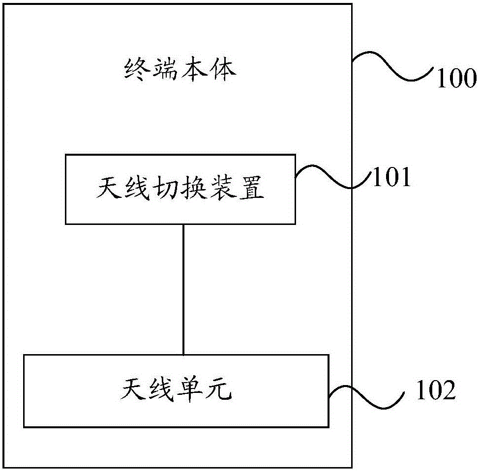
[0036] According to an aspect of the embodiments of the present invention, a mobile terminal is provided, such as figure 1 As shown, the mobile terminal includes:
[0037] A terminal body 100, the terminal body 100 including an antenna unit 102 and an antenna switching device 101 electrically connected to the antenna unit 102;
[0038] Wherein, the terminal body 100 includes a plurality of placement states, the antenna unit 102 includes a plurality of antenna modes, and each of the placement states corresponds to one of the antenna modes, and corresponding to the placement states The antenna efficiency of said antenna mode is higher than the antenna efficiency of other said antenna modes;
[0039] The antenna switching device 101 is used to detect the placement state of the terminal body, and control the antenna mode of the antenna unit 102 to switch to the antenna mode corresponding to the placement state for signal transmission.
[0040] Therefore, when the antenna switchi...
no. 2 example
[0048] The mobile terminal of the embodiment of the present invention includes:
[0049] A terminal body 100, the terminal body 100 including an antenna unit 102 and an antenna switching device 101 electrically connected to the antenna unit 102;
[0050] Wherein, the terminal body 100 includes a plurality of placement states, the antenna unit 102 includes a plurality of antenna modes, and each of the placement states corresponds to one of the antenna modes, and corresponding to the placement states The antenna efficiency of said antenna mode is higher than the antenna efficiency of other said antenna modes;
[0051]The antenna switching device 101 is used to detect the placement state of the terminal body, and control the antenna mode of the antenna unit to switch to the antenna mode corresponding to the placement state for signal transmission.
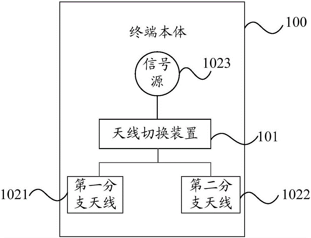
[0052] Wherein, preferably, the terminal body includes a left-hand use state and a right-hand use state, and as figure 2 As shown...
no. 3 example
[0070] An embodiment of the present invention is a mobile terminal with a single antenna structure, and the mobile terminal includes:
[0071] A terminal body 100, the terminal body 100 including an antenna unit 102 and an antenna switching device 101 electrically connected to the antenna unit 102;
[0072]Wherein, the terminal body 100 includes a plurality of placement states, the antenna unit 102 includes a plurality of antenna modes, and each of the placement states corresponds to one of the antenna modes, and corresponding to the placement states The antenna efficiency of said antenna mode is higher than the antenna efficiency of other said antenna modes;
[0073] The antenna switching device 101 is used to detect the placement state of the terminal body, and control the antenna mode of the antenna unit to switch to the antenna mode corresponding to the placement state for signal transmission.
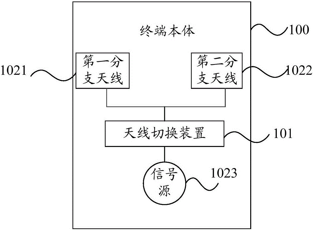
[0074] Wherein, preferably, the terminal body includes a left-hand use state ...
PUM
 Abstract
Description
Claims
Application Information
 - R&D
- Intellectual Property
- Life Sciences
- Materials
- Tech Scout
- Unparalleled Data Quality
- Higher Quality Content
- 60% Fewer Hallucinations
Browse by: Latest US Patents, China's latest patents, Technical Efficacy Thesaurus, Application Domain, Technology Topic, Popular Technical Reports.
© 2025 PatSnap. All rights reserved.Legal|Privacy policy|Modern Slavery Act Transparency Statement|Sitemap|About US| Contact US: help@patsnap.com


