RFID tag with small aperture antenna

a technology of rfid tag and antenna, which is applied in the direction of burglar alarm mechanical actuation, burglar alarm by hand-held articles removal, instruments, etc., can solve the problems of limited life and size relative to the active tag, battery itself may be quite small, and not small enough to overcome the size disadvantage, so as to reduce incident rf power requirements, increase the efficiency of antenna and matching elements, and increase the operational range of the tag

Active Publication Date: 2009-03-10
AMTECH SYST
View PDF77 Cites 33 Cited by
  • Summary
  • Abstract
  • Description
  • Claims
  • Application Information

AI Technical Summary

Benefits of technology

[0027]A related, more specific object of the invention is to provide a RFID tag of extremely compact size and thinness, in the form of a sticker to be adhesively applied to an object whose identity, features, characteristics, authorized use or other aspects are discernible from data stored in tag memory accessible by a RFID reader, and which is adapted to communicate with the reader through a tag antenna of small aperture design, such as a slot antenna, and of polygonal shape with central aperture.
[0028]Other objects include increasing efficiency of antenna and matching elements of the RFID tag to reduce incident RF power requirements and increase operational range of the tag; obtaining wider bandwidth operation of the tag, by some 10% to 20% over current bandwidths; enabling self-adhesion of the tag in highly compact form to the windshield or other surface of a roadway or railway vehicle, with electrical components of the tag designed and positioned for optimum performance of the tag in communication sessions with a RFID reader; incorporating low-cost DC block at the antenna feed terminals to be compatible with a voltage-doubler constructed with Schottky diodes whether external or internal to an integrated circuit (IC) chip of the tag; reducing variability of performance of the tag when mounted on objects with different electrical properties; and rendering the tag capable of use in extremes of vibration, chemicals, dust, temperature and humidity and other adverse atmospheric or ambient conditions.
[0030]According to the most preferred embodiment of the invention, a RFID tag includes a flat, or planar, structure (i.e., relatively smooth with its major surfaces essentially parallel and distinctly greater than its minor surfaces) for adhesive application to the surface of an object to identify the object or a characteristic or feature thereof from data stored in the tag accessible by a RFID reader. The flat structure may be a sticker that incorporates a small aperture antenna, such as a slot antenna, in the form of a polygon having electrically conductive sides. The polygon may be square, rectangular, or in the limit of multiple sides, circular or elliptical, or some other polygonal figure. A central open portion within the polygon constitutes the aperture of the antenna. An integrated circuit chip containing the electronics of the tag is secured to the flat structure within the boundary of the aperture, substantially equidistant from a pair of opposite sides of the polygon, with a pair of conductive impedance matching elements of substantially equal length extending toward each other into the aperture from those opposite sides for minimizing losses in communication between antenna and chip.
[0041]Preferably, the flat structure of the tag and its components are encompassed within a coating, such as a lamination, for protection against damage from ambient environment, and also, with an adhesive side exposed to allow the sticker to be adhesively applied to the object of interest.
[0042]The RFID tag is preferably but not necessarily of the passive type. The small aperture antenna is of a size considerably smaller than a half wavelength of the nominal RF frequency at which the tag is to operate. The antenna's small size and the impedance matching circuit's relatively large shunt impedance (which is considered practically an open circuit with very high impedance, i.e., on the order of 1500 ohms) and relatively small series impedance are significant factors in enabling the RFID tag of the invention to be fabricated in the form of a very thin, extremely compact sticker. Thus, the tag is suitable for self-adhesion to the windshield or other structural component of a vehicle for use in moderate to high speed applications, such as on-the-fly highway toll collection systems and moving rail car asset identification systems. Examples of use of the RFID tag of the invention in other vehicle applications include access to parking spaces in gated parking facilities, electronic vehicle registration stickers, in gated secure facilities and in any application where remote identification of a vehicle is required.
[0045]Another aspect of the invention resides in a method of enabling a vehicle to be detected automatically as being authorized for passage through a restricted lane equipped with a RFID reader, including the step of making available to the vehicle a RFID tag in the form of a planar compact sticker that incorporates a storage medium programmed with authorization data that identifies the vehicle as being permitted to pass through the restricted lane without stopping. The sticker includes a small aperture antenna implemented as a polygon with central aperture for optimized communication of the stored authorization data from the antenna in a backscatter RF signal in response to an interrogating RF signal from the RFID reader within RF communication range of the tag.

Problems solved by technology

The on-board battery of an active RFID tag can give the tag a greater dynamic range than a passive tag, higher data rates and additional functions that require a constant supply of power, but the active tag has the aforementioned disadvantages of limited life and higher cost and size relative to the passive tag.
The battery itself may be quite small, but not small enough to overcome the size disadvantage.
However, the impedance of the tag's electronics and Schottky diode power circuit are poorly matched to antenna designs heretofore proposed for RFID tags.
Conventional matching techniques have been utilized in an effort to reduce the mismatch as much as possible to tolerable levels (e.g., as described in publications such as Application Note 1008, “Designing the Virtual Battery”, Hewlett-Packard Corporation, 1997 (the applicable divested technology group now under the Agilent banner); or U.S. Pat. No. 4,816,839 but they create disadvantages of RFID tag size, cost, capability and efficiency.
But antennas and impedance matching techniques heretofore proposed for passive RFID tags remain burdened by limitations on size, efficiency, cost, bandwidth, and sensitivity to nearby objects such as the surface on which the tag is mounted.
In the specific case of a RFID system consisting of a reader (interrogator) and a tag (transponder) used to complete transactions in high speed applications such as toll collection transactions by identification of authorized vehicles passing the reader in designated lane(s) at highway speed, the system configuration poses serious engineering challenges.
A significant problem encountered in seeking to use prior art RFID tags in high speed applications, such as highway on-the-fly (vehicle non-stop) toll collection systems is the degree of difficulty encountered to design an antenna and impedance matching circuit of reasonably practical size, to optimize the RF communications performance of the tag.
These attributes create a prodigious, virtually impossible task to design an impedance matching circuit of practical size and high energy efficiency for a dipole antenna or other antenna design heretofore proposed for use in a RFID tag.
Generally for antenna designs, the series-matching component may be easy to implement, while the shunt matching component is very difficult to implement because the circuit ground required for the shunt component is normally not well defined and not readily available without degrading antenna performance or necessitating an impractical antenna design.

Method used


Image

  • RFID tag with small aperture antenna
  • RFID tag with small aperture antenna
  • RFID tag with small aperture antenna

Examples


Embodiment Construction

[0059]In describing a preferred embodiment of the invention illustrated in the drawings, certain specific terminology will be used for the sake of clarity. However, the invention is not intended to be limited to that specific terminology, and it is to be understood that the terminology includes all technical equivalents that operate in a similar manner to accomplish the same or similar result.

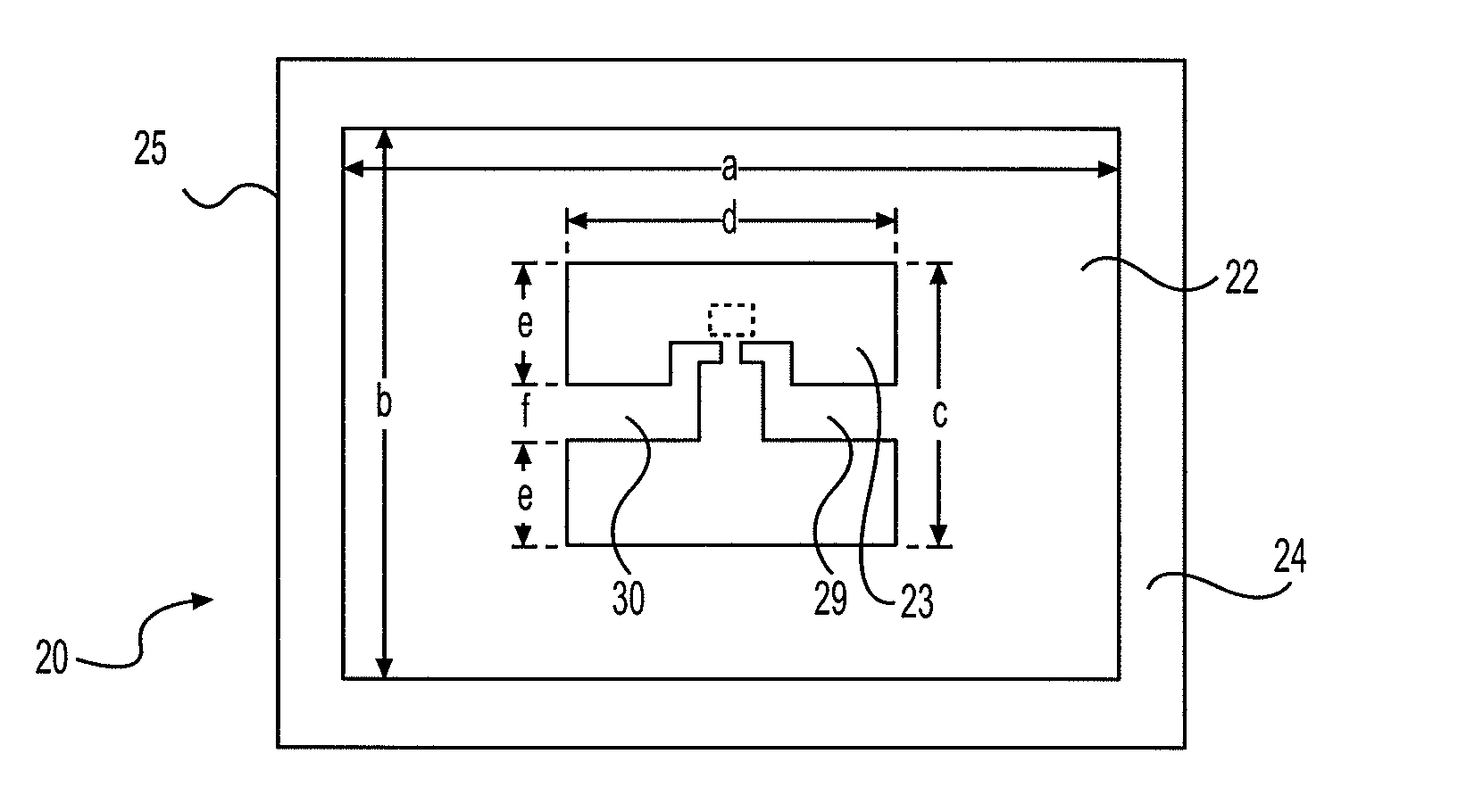
[0060]Reference is now made to FIGS. 5A-5D, which illustrate various views of an exemplary RFID tag 20 of the invention. FIG. 5A is a view without matching circuit elements and RFIC, at one side of a planar passive RFID tag 20 with small aperture (here, slot) antenna element 22 having an aperture 23, at an initial stage of fabrication according to a presently preferred embodiment of the invention. In a presently preferred embodiment, the RFID tag is implemented to be ultimately of sheet sticker-type form intended to be affixed to a surface, preferably the inside surface, of a vehicle's windshie...


PUM


Abstract

A RFID tag to be attached to an object to identify the object or a characteristic or feature thereof from data stored in the tag accessible by a RFID reader includes a relatively flat structure having a small aperture antenna positioned on or proximate the tag in the form of a polygon having electrically conductive sides. The flat structure, which may be fabricated as a sticker or label, incorporates a small aperture antenna, such as a slot antenna, in the form of a polygon having electrically conductive sides. The polygon may be triangular, rectangular, square, elliptical, circular, or other polygonal figure depending on number of its plurality of sides. A constitutes the aperture of the antenna. An integrated circuit chip containing the electronics of the tag is secured to the flat structure within the boundary of the aperture constituting the central open portion within the polygon, and substantially equidistant from a pair of opposite sides of the polygon, with a pair of conductive impedance matching elements of substantially equal length confronting each other in the aperture from the opposite sides. Methods of use are disclosed.

Description

FIELD OF THE INVENTION[0001]The present invention relates generally to radio frequency identification (RFID) systems and methods of operation, and, more particularly, to antenna designs for enhancing the performance of RFID tags. The present invention may also be used to improve performance of other radio systems with non-conventional and highly reactive loads.BACKGROUND OF THE INVENTION[0002]In general, RFID systems consist of a tag or multiplicity of tags implemented to provide information such as identity, features, or characteristics of an object to which the tag is affixed, and to transmit that information via an RF signal to a RFID reader in response to an RF interrogation signal received by the tag from the reader. In most instances of supply chain tagging applications the tag is placed on a container (e.g., a carton, a case or a pallet) for a multiplicity of the same items, in contrast to item-level RFID tagging, in which each individual item is given its own RFID tag. The i...

Claims


Application Information

Patent Timeline
Patent Type & Authority Patents(United States)
IPC IPC(8): G08B13/14G07B15/06
CPCG06K19/07749G06K19/0775G06K19/07786H01Q1/1271H01Q1/2225H01Q13/106
Inventor YOUN, TAI WON
Owner AMTECH SYST
Why Eureka
Try Eureka