
Orthogonal multi-antennas for mobile handsets based on characteristic mode manipulation

a mobile handset and characteristic mode technology, applied in antenna details, antennas, electrical devices, etc., can solve the problems of complex integration of multiple antennas, degrade the mimo performance of terminals, correlation, diversity gain and capacity, etc., to achieve low mutual coupling, low correlation, and high total antenna efficiency

Inactive Publication Date: 2015-01-08
SONY MOBILE COMM INC
View PDF10 Cites 32 Cited by
  • Summary
  • Abstract
  • Description
  • Claims
  • Application Information

AI Technical Summary

Benefits of technology

This patent proposes a new design approach to create uncorrelated and energy-efficient antennas. By manipulating the chassis structure, multiple antennas can be achieved that perform well and have low mutual coupling and correlation. Two different examples of chassis modifications are introduced, with each able to resonate at different frequencies. With proper excitions for these modes, two antennas with low correlations and high efficiency are achieved. The first antenna covers LTE Band 8 and the other covers LTE Band 5 and 8. Overall, this design approach offers a way to create powerful and efficient multi-antenna systems.

Problems solved by technology

Multi-antenna design in mobile handsets at frequency bands below 1 GHz is very challenging, since severe mutual coupling is induced by simultaneous excitation of the chassis' fundamental dipole mode by more than one antenna element.
In user terminals, limited by their relatively small size, integration of multiple antennas is challenging.
Severe mutual coupling between closely spaced terminal antennas degrades the terminals' MIMO performances, such as correlation, diversity gain and capacity.
However, the required matching network is complicated in this multi-antenna system, resulting in limited total antenna efficiencies in practice.
For frequencies below 1 GHz, the existing decoupling techniques are no longer adequate to enable good MIMO antenna design, especially when taking both mutual coupling and antenna bandwidth into consideration.
This is because the mobile chassis is of the right dimensions to be excited and shared by more than one antenna element, making space, angle and polarization diversities difficult to achieve.
However, the bandwidth of the non-chassis-exciting antenna(s) is usually limited due to it being electrically small and not taking advantage of the chassis to radiate.
However, these methods are not used to obtain low frequency multi-antenna designs from the perspective of characteristic mode modification.
From the cellular communication perspective, it is difficult for the bezel mode to satisfy the bandwidth requirement of cellular bands below 1 GHz.
In order to excite a certain mode of the chassis, the biggest challenge is to find the effective feeding structure and feeding locations.
A resonance was successfully created in the simulation; however, the impedance matching was poor due to the small radiation resistance of around 10Ω.
However, the isolation becomes worse as the frequency increases towards 964 MHz.
Though the feeding of the T-strip antenna is at a suitable location to efficiently induce the T-mode at the center frequency of around 900 MHz, it is difficult to guarantee that it does not affect the D-mode over the whole operating band.
As a result, the overall pattern is a combination of the D-mode and the T-mode, deteriorating the orthogonality between the ports and leading to worse isolation than that achieved at lower frequencies.
The monopole antenna also radiates efficiently at LTE Band 5, at which the efficiency of the T-strip antenna is low due to poor impedance matching.
Even at LTE Band 5, the channel capacity of the proposed antenna is higher in general, even though the T-strip antenna is not well matched.
Nevertheless, the hand loss still reduces the mutual coupling to some extent.

Method used


Image

  • Orthogonal multi-antennas for mobile handsets based on characteristic mode manipulation
  • Orthogonal multi-antennas for mobile handsets based on characteristic mode manipulation
  • Orthogonal multi-antennas for mobile handsets based on characteristic mode manipulation

Examples


Embodiment Construction

[0065]Embodiments of the present invention now may be described more fully hereinafter with reference to the accompanying drawings, in which some, but not all, embodiments of the invention are shown. Indeed, the invention may be embodied in many different forms and should not be construed as limited to the embodiments set forth herein; rather, these embodiments are provided so that this disclosure may satisfy applicable legal requirements. Like numbers refer to like elements throughout.

I. INTRODUCTION

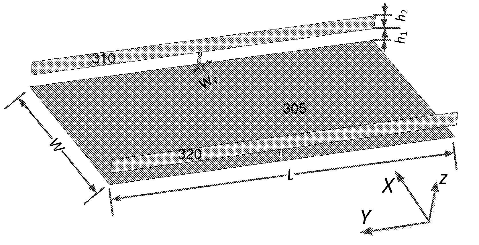
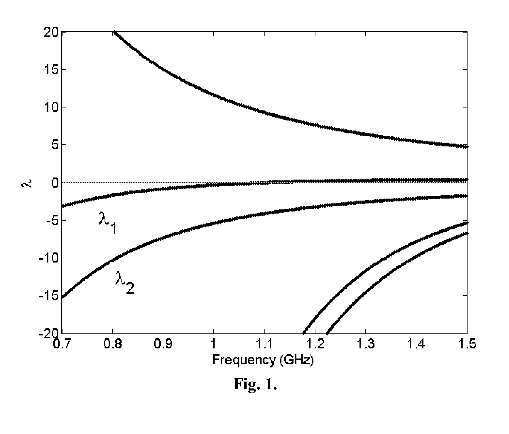
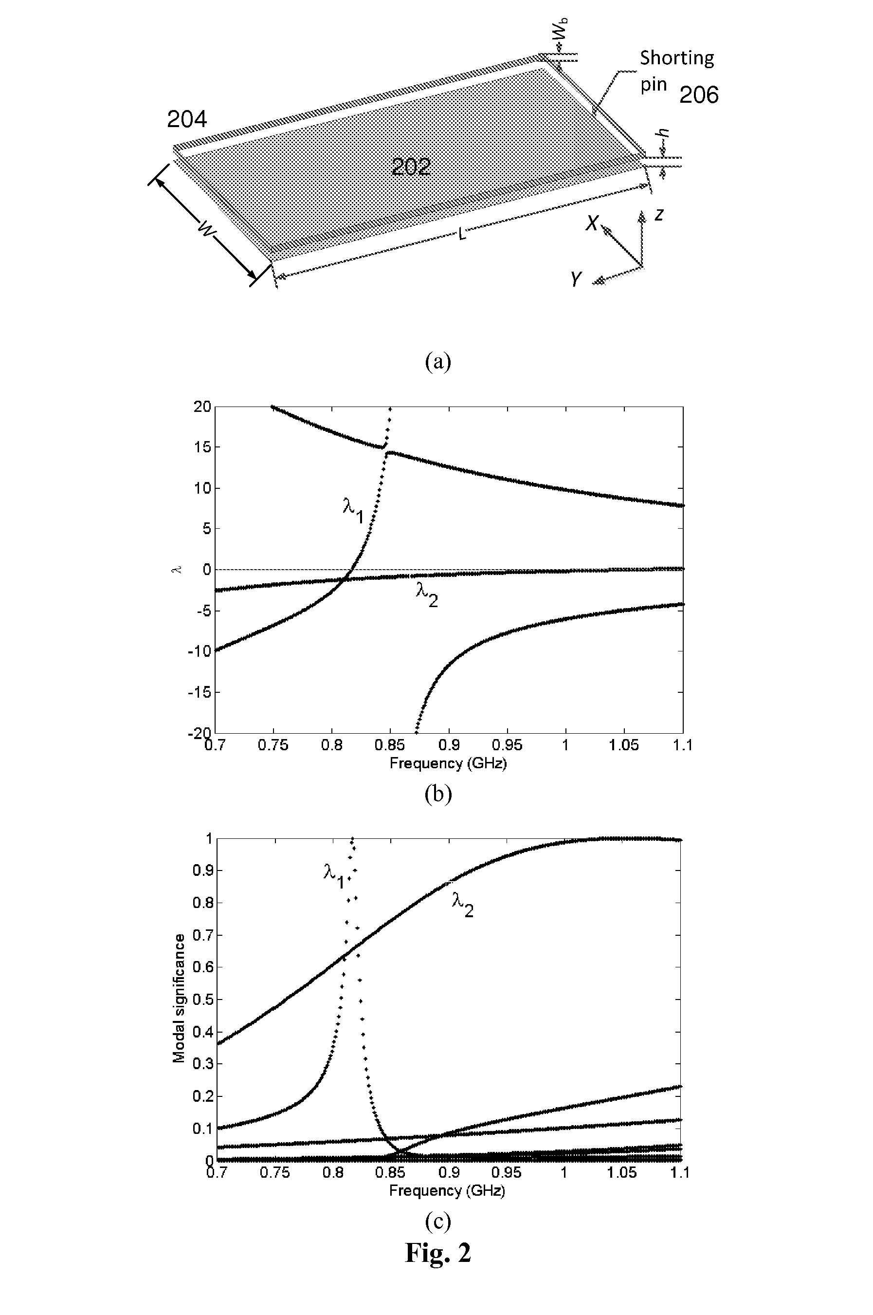
[0066]Multi-antenna design in mobile handsets at frequency bands below 1 GHz is very challenging, since severe mutual coupling is induced by simultaneous excitation of the chassis' fundamental dipole mode by more than one antenna element. According to some embodiments of this invention, a novel multi-antenna design approach is proposed to obtain uncorrelated antennas. By manipulating the chassis structure, more than one characteristic mode is enabled to resonate at frequency below 1 GHz...


PUM


Abstract

A novel multi-antenna design approach is proposed to obtain uncorrelated and energy efficient antennas. By manipulating the chassis, more than one characteristic mode is enabled to resonate at frequency below 1 GHz. With proper excitations for different characteristic modes, which are inherently orthogonal to each other, well performed multiple antennas with low mutual coupling and correlation are achieved. Three examples of chassis manipulation, a bezel structure and two T-shaped structures with metal strips along the chassis, are introduced. With efficient excitations of the fundamental dipole mode and T-strip mode, two antennas with low correlations and high total antenna efficiencies are achieved, with both antennas covering one or more of the low frequency LTE bands 5, 6, 8, 12, 13, 14, 17, 18, 19, and 20 in combination with one or more of high frequency LTE bands 1, 2, 3, 4, 9, 10, 11, 15, 16, 21, 23, 24, and 25.

Description

CROSS-REFERENCE TO RELATED APPLICATIONS[0001]This application claims priority to U.S. Provisional Patent Application Ser. No. 61 / 843,172, filed Jul. 5, 2013, entitled “Orthogonal Multi-Antennas For Mobile Handsets Based On Characteristic Mode Manipulation,” the entirety which is incorporated herein by reference.BACKGROUND[0002]Multi-antenna design in mobile handsets at frequency bands below 1 GHz is very challenging, since severe mutual coupling is induced by simultaneous excitation of the chassis' fundamental dipole mode by more than one antenna element. Severe mutual coupling through the chassis' fundamental dipole mode results in poor antenna efficiency and highly correlated received signals, leading to poor multiple-input multiple-output (MIMO) system performance. Therefore, there is a need for a novel multi-antenna design approach to obtain uncorrelated and energy efficient antennas.BRIEF SUMMARY[0003]According to some embodiments of this invention, a novel multi-antenna design...

Claims


Application Information

Patent Timeline
Patent Type & Authority Applications(United States)
IPC IPC(8): H01Q5/00
CPCH01Q5/0024H01Q25/04H01Q1/243H01Q5/30H01Q5/342H01Q21/28
Inventor LAU, BUON KIONGLI, HUIMIERS, ZACHARY
Owner SONY MOBILE COMM INC
Learn More