Slotted NMR antenna cover

a technology of antenna cover and nmr, which is applied in the direction of reradiation, measurement using nmr, instruments, etc., can solve the problems of inability to achieve nmr, badly affected nmr method, etc., and achieve the effect of increasing the efficiency of nmr antenna, and reducing eddy current concentration

Inactive Publication Date: 2005-01-04
BAKER HUGHES INC
View PDF21 Cites 30 Cited by
  • Summary
  • Abstract
  • Description
  • Claims
  • Application Information

AI Technical Summary

Benefits of technology

The apparatus and method of the present invention overcome the disadvantages of known down hole NMR tools. The present invention provides a slotted NMR antenna cover for improved mechanical ruggedness during transmission and reception of NMR signals in a down hole environment during either MWD or wire line operations. In one aspect of the present invention a slotted NMR antenna cover is presented, comprising an elongated tubular structure with longitudinal gaps or slots filled with a RF transmissive or non-conductive material. In another embodiment, the slots are filled at the slot ends with soft magnetic material to improve efficiency of the antenna. The ribs between the slots (in the following simply called ribs) have edges that are radial convex to reduce power dissipation in eddy currents induced by electromagnetic energy entering and leaving the slots surrounding the antenna. In another embodiment, the antenna cover is RF transmissive on only a portion of the antenna, via slots or transmissive material, so that the antenna cover can be used to allow RF transmission from the antenna in a side looking or beam pattern restricted mode only. The slotted NMR antenna cover can be deployed in a MWD environment on a tool having a fixed attachment to the drill string or rotationally attached to the drill string on a non-rotating sleeve surrounding the drill string. The present invention can also be deployed on a NMR tool deployed in a borehole via a wire line.
In one preferred embodiment, the slotted antenna cover includes a plurality of axial slots in a metal skeletal structure. The slots are filled with non-conducting or poorly-conducting material, which allow for the passage of the interrogating electromagnetic field from the central bore of the measurement tubular to the borehole and surrounding formation. In another preferred embodiment, the ends of the slots are filled with a soft magnetic material such as ferrite or powdered iron bound in an epoxy binder. The soft magnetic material lowers the magnetic reluctance of the RF transmission and reception path through the antenna cover slots, thereby increasing the efficiency of the antenna and slotted antenna cover combination. The slot edges are smoothed and curved to decrease power losses associated to the eddy currents that would accumulate at a sharp edge.
It is one objective of the present invention to provide an improved measurement-while-drilling NMR system which utilizes a slotted NMR antenna cover which is at least partially formed of metal with the material advantage of strength, toughness and resistance to wear and abrasion but at the same time enables alternating magnetic flux to pass through this cover by also providing slots filled with a material which is non-conducting or poorly-conducting. The present invention also increases the efficiency of an NMR antenna by reducing eddy currents induced by the incoming and outgoing magnetic field. Longitudinal slots are formed in the antenna cover. The slots are air-filled or filled with materials of varying electromagnetic and electrical properties. The edges of the antenna cover ribs are curved in radial direction to reduce concentration of eddy currents, which would migrate toward a sharper edge on the rib if the rib edge were not curved. A soft magnetic material is inserted in the ends of each slot to reduce the reluctance encountered by RF electromagnetic energy incoming and outgoing through the NMR antenna cover slots. This soft magnetic material can be for example ferrite or powdered iron or preferably layered material made of amorphous metal ribbon or other very thin ferromagnetic foil with high magnetic permeability. These and other objectives are achieved as is now described in the context of a NMR MWD operation.

Problems solved by technology

Up to now it was generally assumed that such a metal cover is not feasible for NMR as the NMR method would suffer badly from any RF power losses in such a cover, while transmitting and while receiving RF.

Method used


Image

  • Slotted NMR antenna cover
  • Slotted NMR antenna cover
  • Slotted NMR antenna cover

Examples


Embodiment Construction

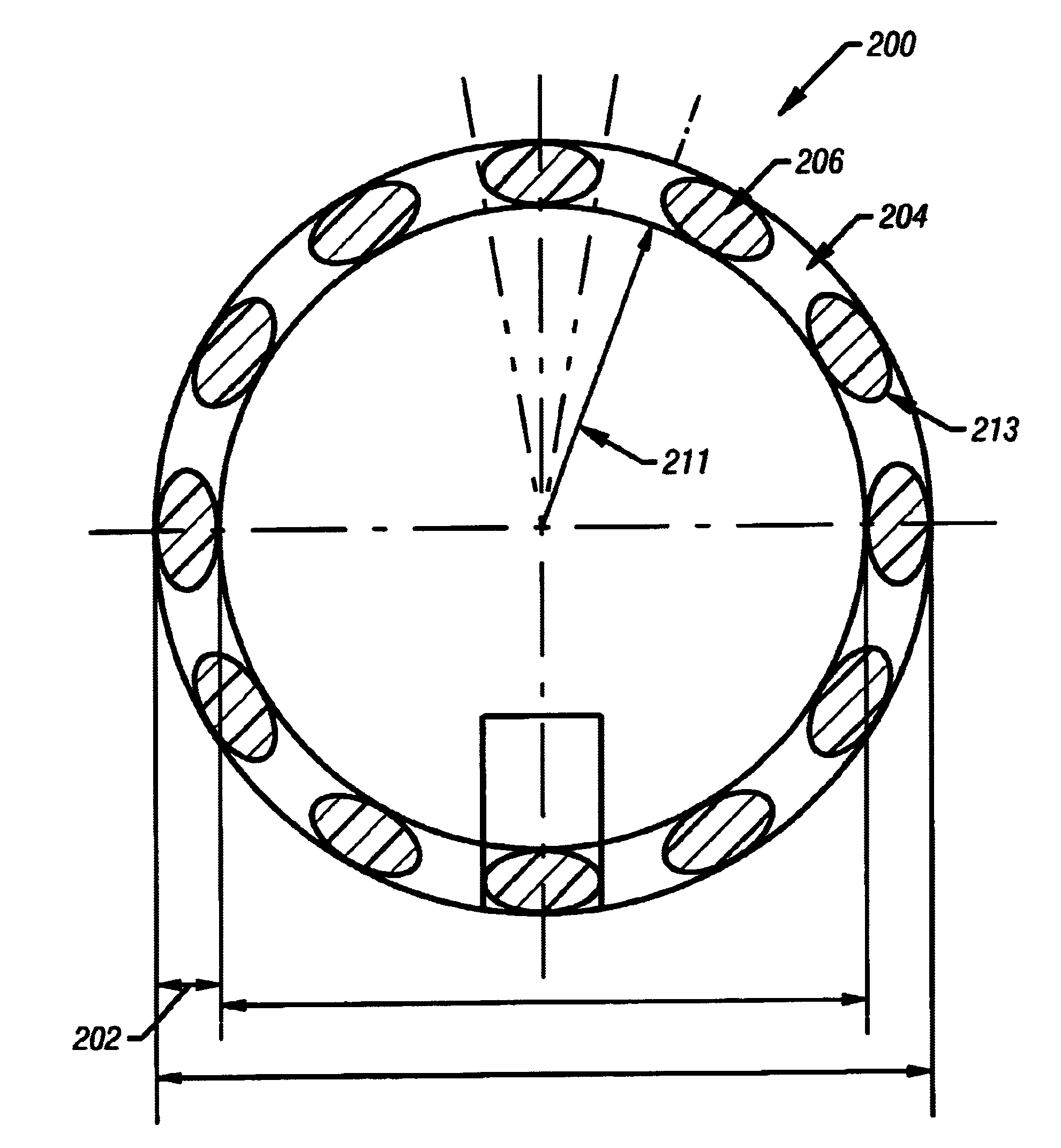
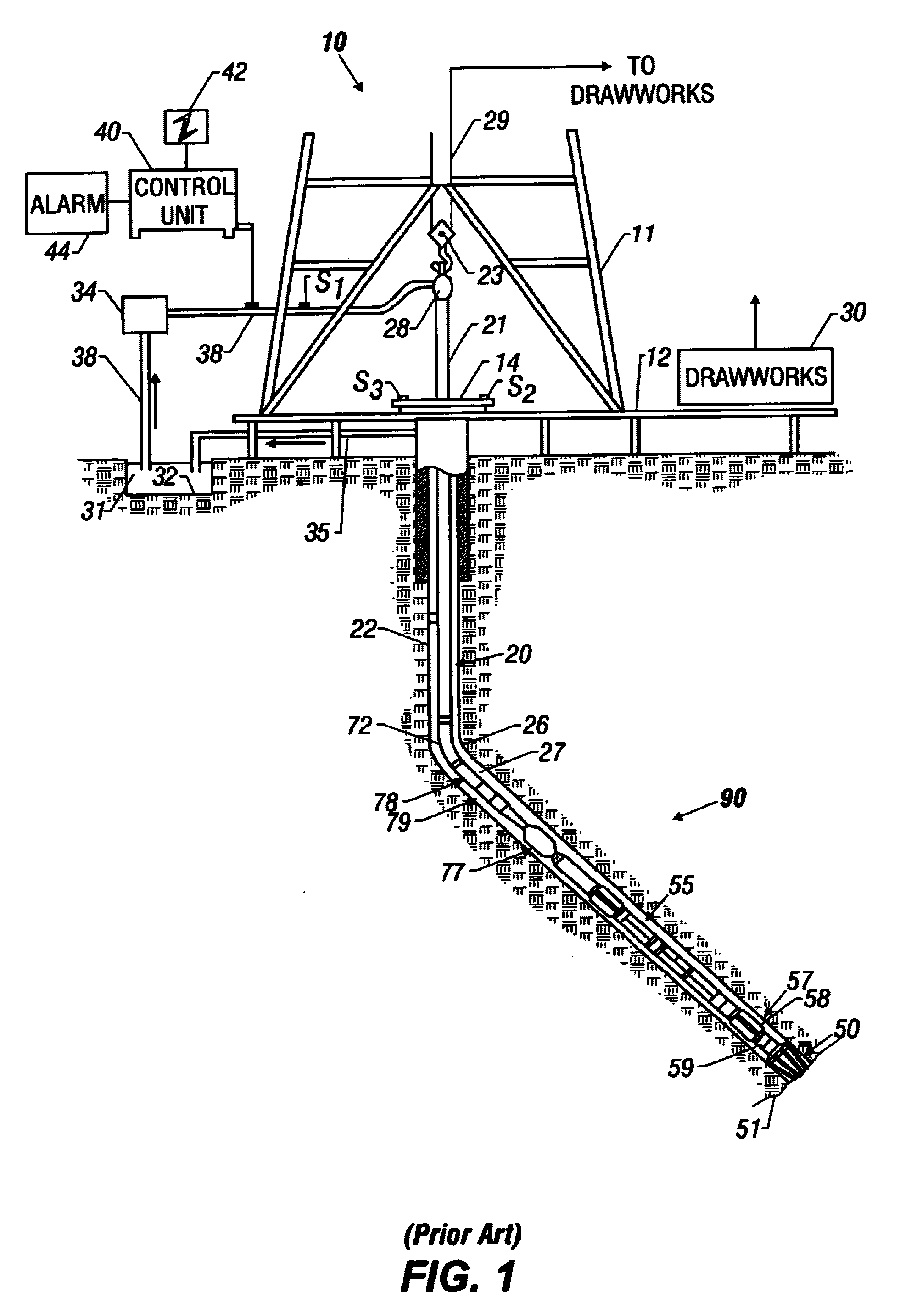
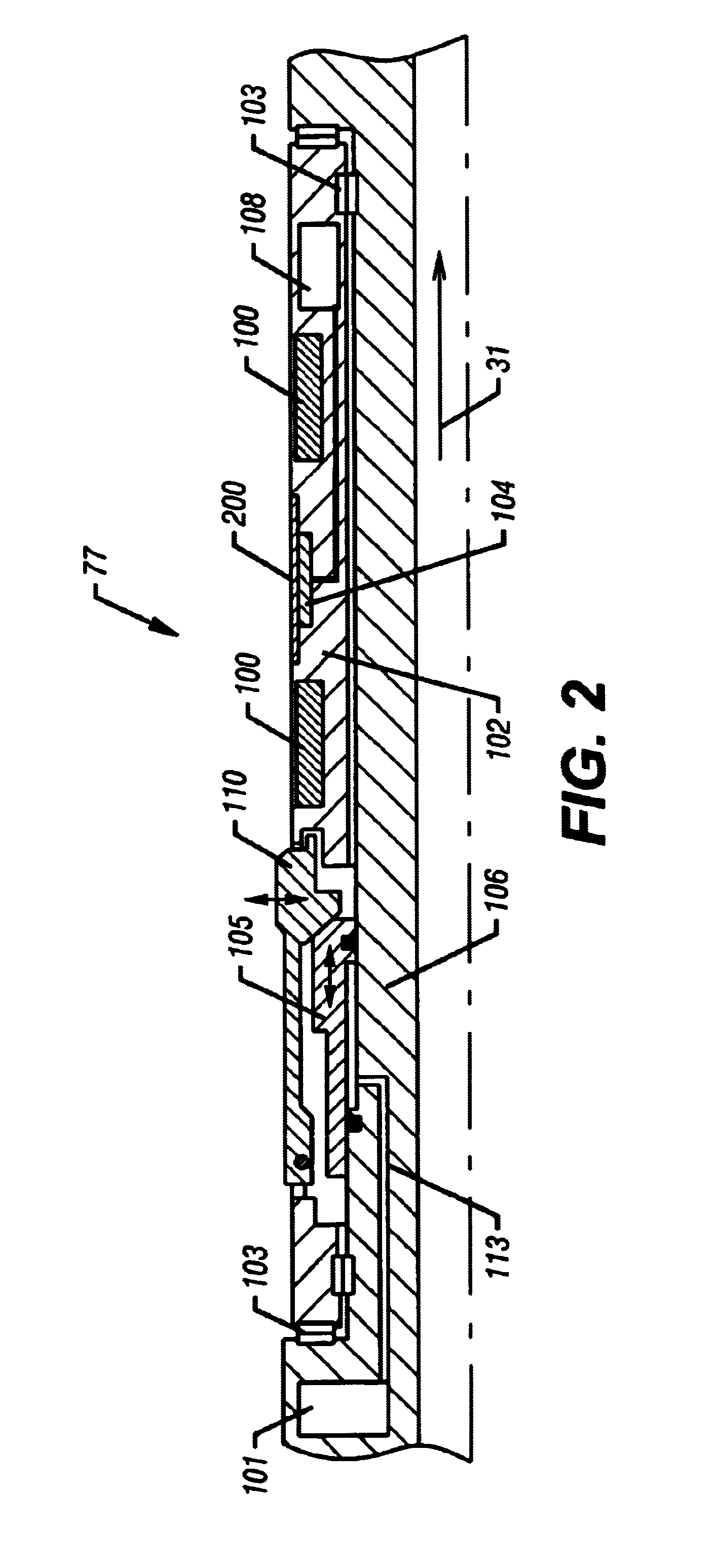
The present invention can be deployed in a MWD operation on a non-rotating sleeve surrounding the drill string or fixed to the drill string. The present invention may also be deployed on a wire line. The present invention provides a rugged NMR antenna cover, which in a preferred embodiment is a slotted metal cylinder surrounding the antenna to protect it from abrasive effects of drilling. RF transmissive portions are formed in the antenna cover to enable RF radiation to enter and exit the RF transmissive portions. The RF electromagnetic flux exits one end of the transmissive portion or slot, passes through the formation and reenters the other end of the transmissive portion or slot, thus substantially canceling eddy currents induced by the electromagnetic fields entering and leaving the antenna cover slots. Or otherwise expressed the net flow of field through a slot is zero and for this reason no eddy current is formed around the slot.

FIG. 1 illustrates a schematic diagram of a dril...


PUM


Abstract

A slotted NMR antenna cover for improved mechanical ruggedness during transmission and reception of NMR signals in a down hole environment during either MWD or wire line operations. A NMR slotted antenna cover is provided comprising an elongated tubular structure with longitudinal gaps or slots filled with a RF transmissive or non-conductive material. The slots can befilled at the slot ends with soft magnetic material to improve efficiency of the antenna. The slots are radial concave to reduce eddy currents induced by alternating magnetic flux entering and leaving the slots surrounding the antenna. In another embodiment, the antenna cover is RF transmissive on only a portion of the antenna, via slots or transmissive material, so that the antenna cover can be used to allow RF transmission from the antenna in a side looking or beam pattern restricted mode only.

Description

BACKGROUND OF THE INVENTION1. Field of the InventionThe present invention relates to a slotted antenna cover for protection of the RF antenna of a nuclear magnetic resonance (NMR) tool.2. Background of the Related ArtTo obtain hydrocarbons such as oil and gas, a drilling assembly (also referred to as the “bottom hole assembly” or the “BHA”) carrying a drill bit at its bottom end is conveyed into the well bore or borehole. The drilling assembly is usually conveyed into the well bore by a coiled-tubing or a drill pipe. In the case of the coiled-tubing, the drill bit is rotated by a drilling motor or “mud motor” which provides rotational force when a drilling fluid is pumped from the surface into the coiled-tubing. In the case of the drill pipe, it is rotated by a power source (usually an electric motor) at the surface, which rotates the drill pipe and thus the drill bit.Bottom hole assemblies (“BHA”) generally include several formation evaluation sensors for determining various parame...

Claims


Application Information

Patent Timeline
Patent Type & Authority Patents(United States)
IPC IPC(8): G01V3/32G01R33/34G01V3/18G01R33/44
CPCG01V3/32G01R33/34053
Inventor KRUSPE, THOMASBLANZ, MARTINROTTENGATTER, PETER
Owner BAKER HUGHES INC
Why Eureka
Try Eureka