Printed broadband terminal antenna

A terminal antenna, broadband technology, applied in the field of broadband terminal antenna, to achieve the effect of easy realization, easy processing, and wide working bandwidth

Inactive Publication Date: 2011-12-14
UNIV OF ELECTRONICS SCI & TECH OF CHINA
View PDF1 Cites 28 Cited by
  • Summary
  • Abstract
  • Description
  • Claims
  • Application Information

AI Technical Summary

Problems solved by technology

The existing matching circuit is formed by lumped components, such as chip inductors and capacitors. This matching circuit composed of lumped components can only perform impedance matching on a certain frequency point.

Method used


Image

  • Printed broadband terminal antenna
  • Printed broadband terminal antenna
  • Printed broadband terminal antenna

Examples


Embodiment 1

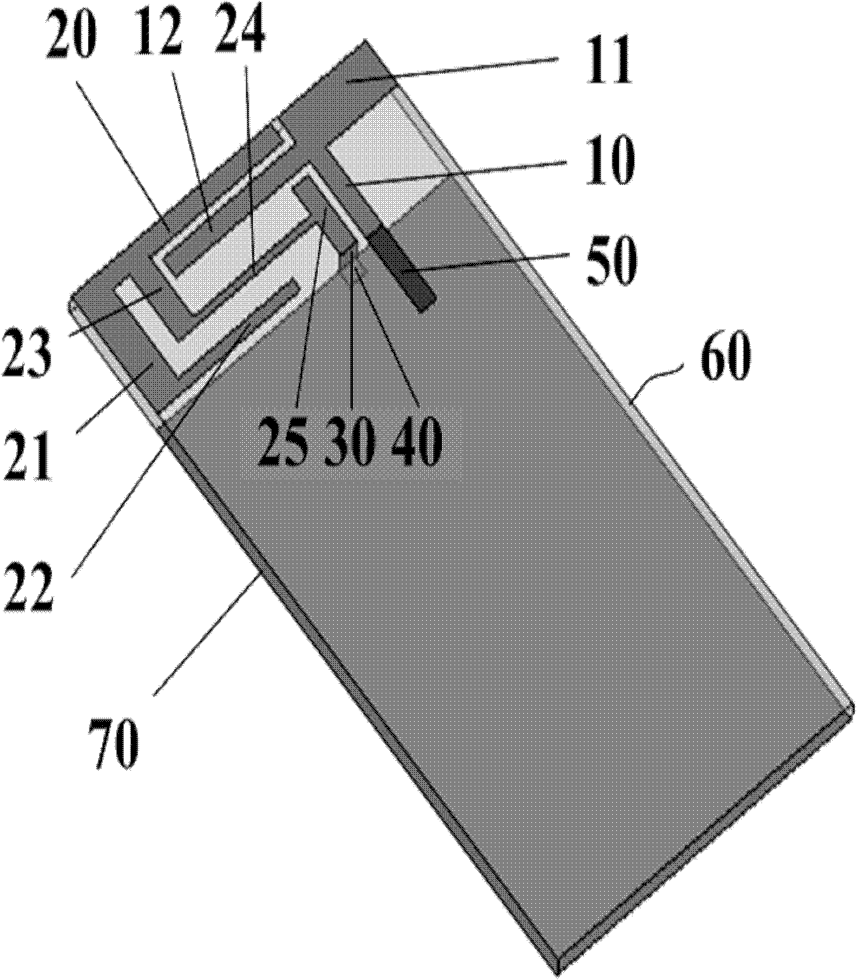
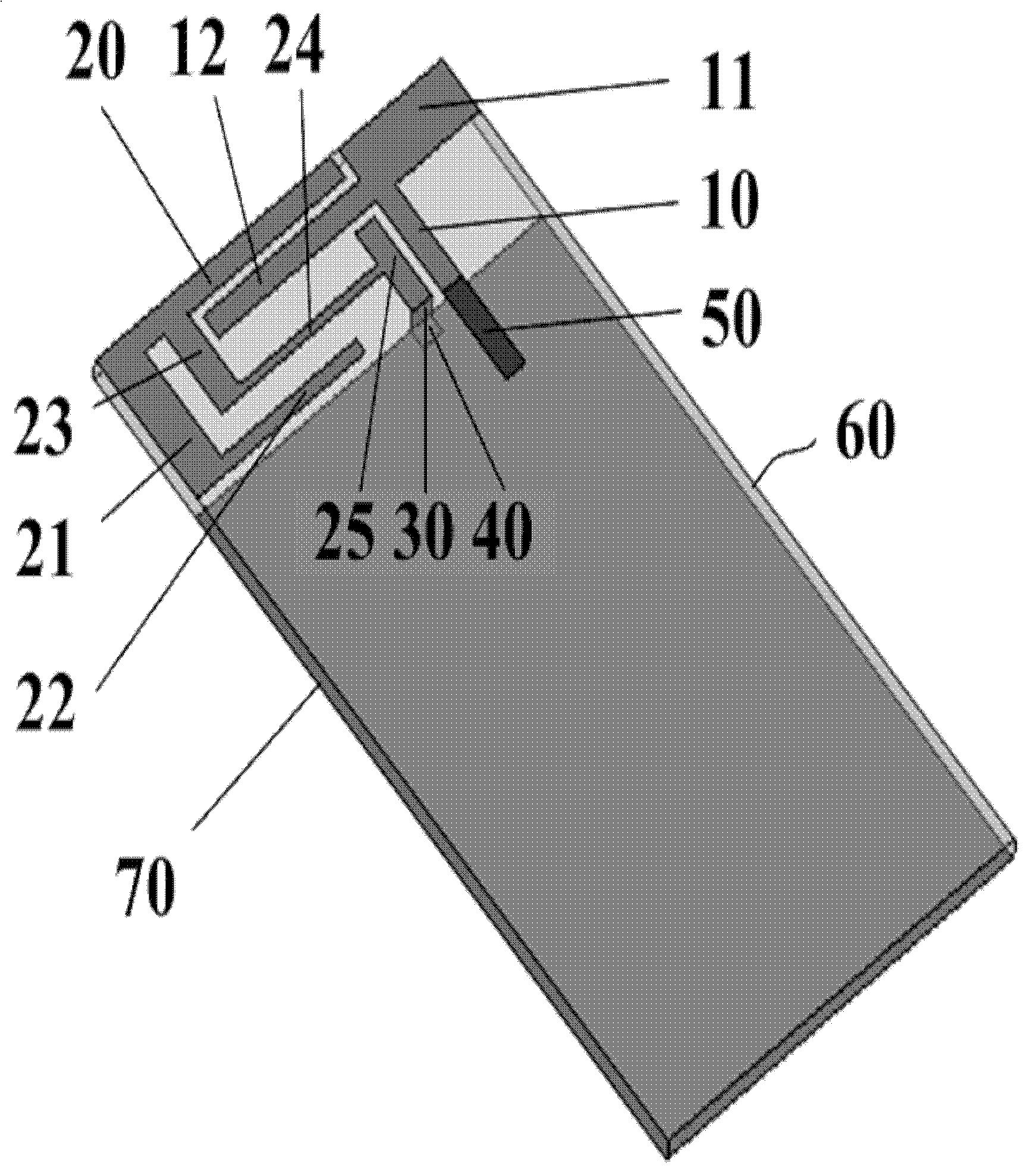
[0022] Such as figure 1 As shown, the terminal antenna includes: a first bent metal strip group (10, 11, 12), a second bent metal strip group (20, 21, 22, 23, 24, 25), a grounding wire 30, and a grounding piece 40 , 50 ohm microstrip feeder 50, printed circuit board 60 and metal ground 70 printed on the other side of the printed circuit board;

[0023] One end of the grounding wire 30 is connected to the above-mentioned second bent metal strip group (20, 21, 22, 23, 24, 25), the other end is connected to the grounding piece 40, and the other end of the grounding piece 40 is connected to the metal ground 70;

[0024] One end of the ground wire 30 is connected to an edge of the second bent metal strip group (20, 21, 22, 23, 24, 25), or connected to the second bent metal strip group (20, 21, 22, 23, 24, 25) on a certain surface; the other end of the ground wire 30 can be connected to an edge of the ground sheet 40, or connected to the surface of the ground sheet 40;

[0025] On...

Embodiment 2

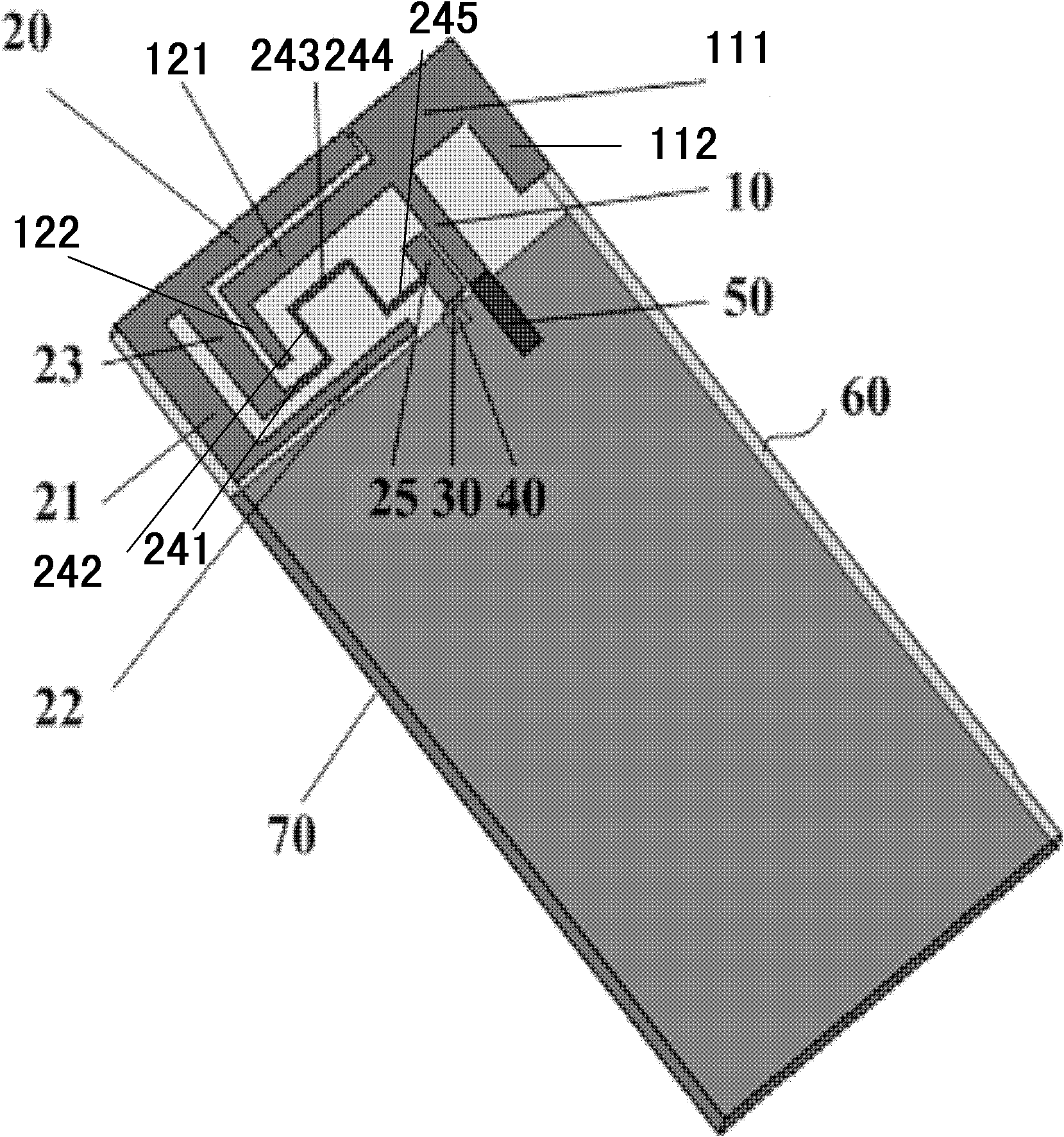
[0034] Such as figure 2 The terminal antenna shown is optimized on the basis of Embodiment 1. In order to optimize the debugging results and further reduce the area occupied by the antenna, figure 2 In the shown terminal antenna, the original second metal strip 11 and the third metal strip 12 are respectively extended downward for a certain distance. The second metal strip 10 is composed of a first metal strip assembly 111 and a second metal strip assembly 112. The first The metal strip assembly is orthogonally connected to the second metal strip assembly; the third metal strip 12 is composed of a third metal strip assembly 121 and a fourth metal strip assembly 122, and the third metal strip assembly is orthogonally connected to the fourth metal strip assembly; The function of the metal strip is to extend the resonance length of the corresponding frequency point, so that the resonance point moves to the left (lower the resonance frequency). At the same time, the coupling am...


PUM


Abstract

The invention provides a printing boardband terminal antenna with smaller occupying space. The printing boardband terminal antenna comprises a first bent metal strip group and a second bent metal strip group; a gap is formed between the first bent metal strip group and the second bent metal strip group; a microstrip feed line is used for directly feeding electricity to the first bent metal strip group so as to excite a high-frequency current on the first bent metal strip group to form resonance; and a high-frequency current on the second bent metal strip group is excited by capacitive coupling of the gap between the first bent metal strip group and the second bent metal strip group to form resonance. According to the invention, the first bent metal strip group and the second bent metal strip group are not directly connected, a plurality of frequency points are matched according to the distributed parameter effect of the gap between the two metal strip groups, and therefore the bandwidth can be widened in a larger extent. Therefore, the size occupied by the antenna can be reduced; in addition, a dedicated matching circuit and a special substrate material are not required in the invention.

Description

technical field [0001] The invention belongs to the technical field of antennas, and in particular relates to a broadband terminal antenna. Background technique [0002] At present, the development of mobile communication technology has made the sense of space distance between us smaller and smaller. With the use of relatively small electronic technology products, we can exchange information with each other at any time, which is inseparable from the use of antennas. At the same time, with the development of personal communication services, people's requirements for wireless products are becoming more and more stringent, which is mainly reflected in two aspects: broadband and miniaturization. In particular, the development of high-speed data transmission systems and military broadband wireless systems requires antennas to have wider bandwidths. In view of this, in order to improve the working performance and working efficiency of wireless communication receiving and sending ...

Claims


Application Information

Patent Timeline
Patent Type & Authority Applications(China)
IPC IPC(8): H01Q1/38H01Q1/48
Inventor 陈金华班永灵应李俊
Owner UNIV OF ELECTRONICS SCI & TECH OF CHINA
Why Eureka
Try Eureka