Portable electric equipment inspection device

A technology of electric equipment and inspection devices, which is applied in mechanical equipment, televisions, electrical components, etc., can solve problems such as hidden defects of electronic components, affect the normal use of electrical cabinets, and difficult inspection of components, etc., and achieve good market use effects and promotion Foreground, improve inspection work efficiency, effect of simple structure

Active Publication Date: 2016-08-03
CHINA SINOGY ELECTRIC ENG
View PDF17 Cites 11 Cited by
  • Summary
  • Abstract
  • Description
  • Claims
  • Application Information

AI Technical Summary

Problems solved by technology

[0002] At present, during the long-term use of the electrical cabinet, due to the influence of various factors, various hidden dangers of defects often occur in the electronic components inside the cabinet.
When the power workers inspect the live running equipment, it is more convenient to check the components located on the front of the cabinet, and they can understand the damage of the components through visual observation, but it is more diff

Method used


Image

  • Portable electric equipment inspection device
  • Portable electric equipment inspection device
  • Portable electric equipment inspection device

Examples


Embodiment 1

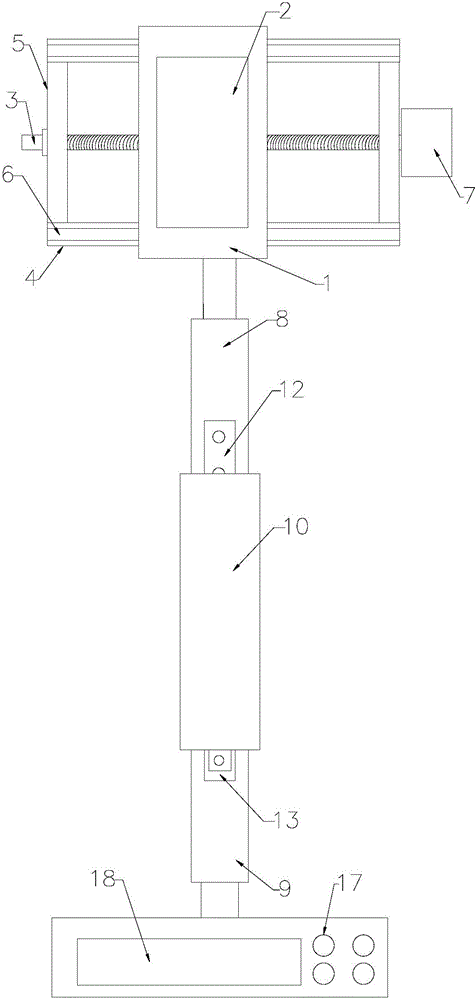
[0043] see figure 1 , figure 2 , Figure 4 to Figure 15 , In this example, it includes a video capture device, a monitoring device, and a support device. The top of the monitoring device is connected to the support device and the video capture device in sequence from bottom to top. It is characterized in that: the video capture device includes a guide frame body, a base 1. The camera 2, the front side of the guide frame body is horizontally connected to the back side of the base 1, and the camera 2 is fixed on the front side of the base 1. In this example, the guide frame body includes a square frame composed of two upper and lower horizontal bars 4 and two left and right vertical bars 5. The horizontal bar 4 is provided with a sliding rail 6 along the length of the horizontal bar 4, which is connected with the sliding rail 6. A sliding block is provided on the base 1 corresponding to the rail 6 , and the sliding block is nested in the sliding rail 6 to realize the sliding ...

Embodiment 2

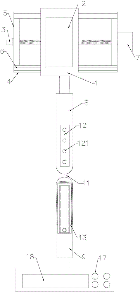
[0055] This example is basically the same as Example 1, except that in the bendable support device described in this example, the upper support rod 8 and the lower support rod 9 are axially connected, and the upper support rod 8 is wound vertically upward and downward. The shaft joint of the support rod 9 rotates.

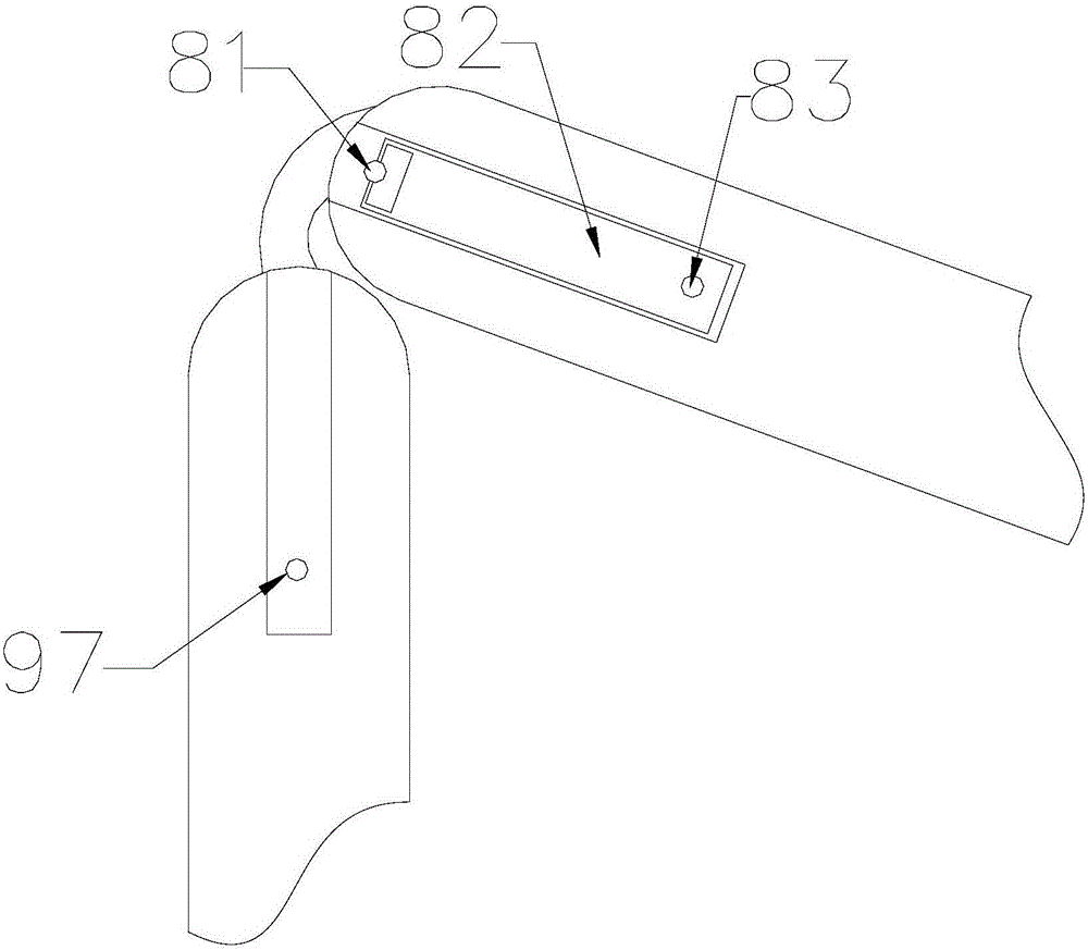
[0056] In addition, the straightening device in this example is to set an upper embedding groove along the length direction of the upper supporting rod 8 at the lower part of the outer wall of the upper supporting rod 8, and this upper embedding groove and the groove 12 are located on different sides of the upper supporting rod 8, A lower insert groove is set along the length direction of the lower support bar 9 at the upper part of the outer wall of the corresponding lower support bar 9; The other end of the straight rod 82 is provided with a cylindrical member 97; and one end of the straight rod 82 is rotatably connected to the upper or lower embedded groove in w...


PUM


Abstract

The invention relates to the technical field of mechanical equipment, specifically a portable electric equipment inspection device. The device comprises a video acquiring device, a monitoring device and a supporting device; the top of the monitoring device is orderly connected with the supporting device and the video acquiring device from bottom to top. The device is characterized by comprising a guiding frame body, a base and a camera; the supporting device adopts a bent supporting device; the bent supporting device is further provided with a straightening device capable of enabling an upper supporting rod and a lower supporting rod to be on the same perpendicular line; the bent supporting device is further provided with an angle regulating device for regulating an included angle between the upper supporting rod and the lower supporting rod. Compared with the prior art, the inspection device disclosed by the invention can implement the electrified polling working to all electric components at the front side, the rear side and the side part of an electric cabinet body.

Description

technical field [0001] The invention relates to the technical field of mechanical equipment, in particular to a portable power equipment inspection device. Background technique [0002] At present, during the long-term use of the electrical cabinet, due to the influence of various factors, various hidden dangers of defects often occur in the electronic components inside the cabinet. When the electric staff inspects the live equipment, it is more convenient to inspect the components located on the front of the cabinet, and they can understand the damage of the components through visual observation, but it is more difficult to inspect the components located on the back of the cabinet. Especially when the outdoor electrical cabinet is running with electricity, if the electric staff wants to inspect the internal electronic components, they can only power off the power equipment first, and then disassemble and inspect the components located on the back of the cabinet. It reduces...

Claims


Application Information

Patent Timeline
IPC IPC(8): H04N7/18F16M11/40F16M11/38F16M11/28F16M11/14F16M11/20
CPCF16M11/14F16M11/2021F16M11/28F16M11/38F16M11/40H04N7/183
Inventor 杨浩亮王广波苑惠刘万山刘军文秦娜娜焦红超
Owner CHINA SINOGY ELECTRIC ENG
Why Eureka
Try Eureka