
Steering spline telescoping shaft, and steering device

A rolling radius, adhesion technology, applied in the direction of brakes, external condition input parameters, control devices, etc.

Active Publication Date: 2016-08-03
MICHELIN & CO CIE GEN DES ESTAB MICHELIN
View PDF8 Cites 12 Cited by
  • Summary
  • Abstract
  • Description
  • Claims
  • Application Information

AI Technical Summary

Problems solved by technology

However, this method requires a large slip zone in the contact area, and the method only produces information when the vehicle is already close to the conditions at which the tires start to slide on the ground
Arguably, such an alert is too late to be used as a driving aid

Method used


Image

  • Steering spline telescoping shaft, and steering device
  • Steering spline telescoping shaft, and steering device
  • Steering spline telescoping shaft, and steering device

Examples


Embodiment Construction

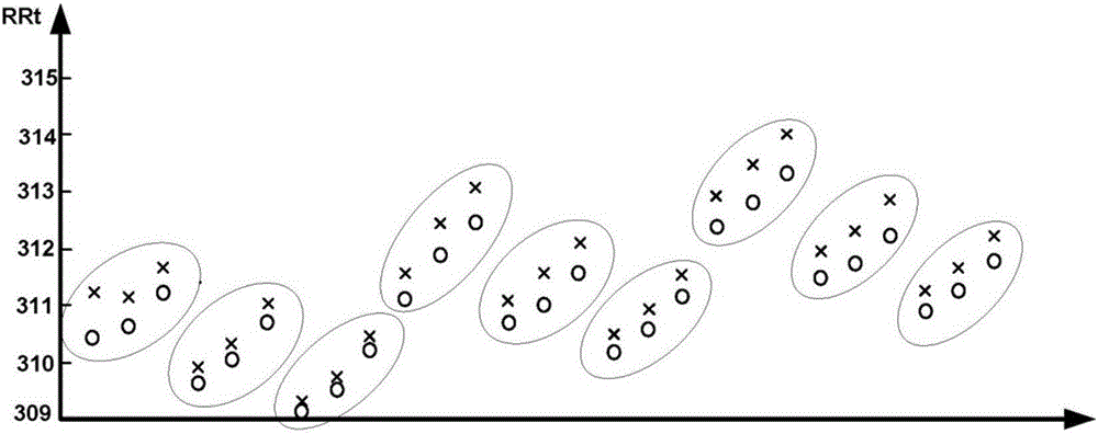
[0062] figure 1 shows the phenomenon on which the invention is based, by which it is conceivable to measure the non-driven and non-steered wheels successively at 0 and T while the vehicle is traveling in a straight line at a constant speed 1 Driving on wet ground between, T 1 with T 2 Driving on dry ground between and on T 2 The rolling radius when driving on wet ground again afterwards.

[0063] It can be seen that the rolling radius RRt increases by 0.5 mm when changing from driving on wet to dry ground and decreases by the same amount when changing from driving on dry to wet ground.

[0064] figure 2 This experimental protocol was reproduced for different speeds, actual load conditions and inflation pressures. It can still be seen that the rolling radius changes when changing from being on a dry ground (indicated by a cross) to being on a wet ground (indicated by a circle) and vice versa.

[0065] The method then includes establishing the rolling radius from an equat...


PUM


Abstract

A spline telescoping shaft is provided with an inner shaft including a male spline, and a cylindrical outer shaft including a female spline. The surface of at least one of the splines is provided with a resin coating. Profile shift coefficient e, the number of teeth Z, module m, reference pitch diameter PCD, the tip diameter d1 and root diameter d2 of the male spline, and the tip diameter D1 and root diameter D2 of the female spline have the relationships according to expressions (1) to (8): m(Z + 4) > d1 > m(Z + 2) (1); mZ > d2 > m(Z - 1) (2); m(Z + 4) > D2 > m(Z + 2) (3); mZ > D1 > m(Z - 1) (4); D2 > d1 (5); D1 > d2 (6); PCD = mZ (7); and 0.4 < e < 1.1 (8).

Description

technical field [0001] The field to which the invention relates is that of tires for automotive vehicles. More specifically, the invention relates to real-time estimation of vehicle-to-ground adhesion conditions so that the driver or on-board safety systems can be warned of changes in rolling conditions that may put the vehicle and its occupants at risk. Background technique [0002] Various systems for estimating the adhesion of a tire to the ground have been described. [0003] The first systems for measuring potential adhesion provided by the original equipment manufacturers were based on ABS-type systems and ESP-type controls. These systems construct the tire's coefficient of adhesion to the ground by calculating it indirectly, rather than measuring the force generated by the contact area. [0004] More recently, document EP 1076235 proposes the use of sensors to measure the tangential force experienced by a given sculptural element when it enters the contact zone, the...

Claims


Application Information

Patent Timeline
Patent Type & Authority Applications(China)
IPC IPC(8): B60W40/068
CPCB60W40/068B60T2210/12B60W2520/10B60W2520/28B60T8/172B60W2556/50B60W2552/40B60W2555/20B60W40/12B60W40/13
Inventor M·迪韦尼耶
Owner MICHELIN & CO CIE GEN DES ESTAB MICHELIN
Learn More