Check patentability & draft patents in minutes with Patsnap Eureka AI!

Backlight module

A technology of backlight module and light source, which is applied in optics, nonlinear optics, instruments, etc., can solve the problems of image difference and brightness uniformity, and achieve the effect of improving brightness uniformity

Active Publication Date: 2019-08-23
AU OPTRONICS CORP
View PDF9 Cites 0 Cited by
  • Summary
  • Abstract
  • Description
  • Claims
  • Application Information

AI Technical Summary

Problems solved by technology

However, in the existing methods, the deformation (shrinkage) of the optical film or the leakage of blue light due to the arrangement of the optical film and the light source and the distance between the two will lead to poor brightness of the picture. homogenization

Method used


Image

  • Backlight module
  • Backlight module
  • Backlight module

Examples


Embodiment Construction

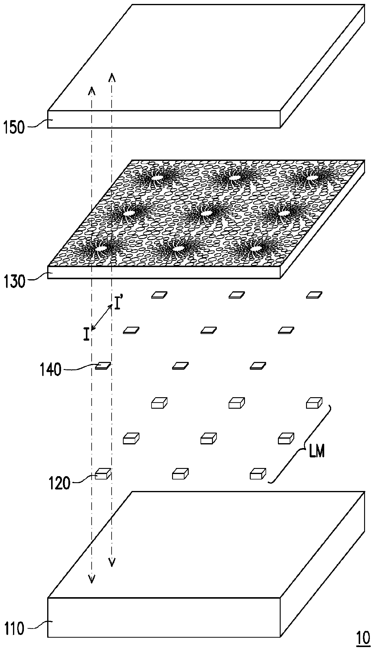
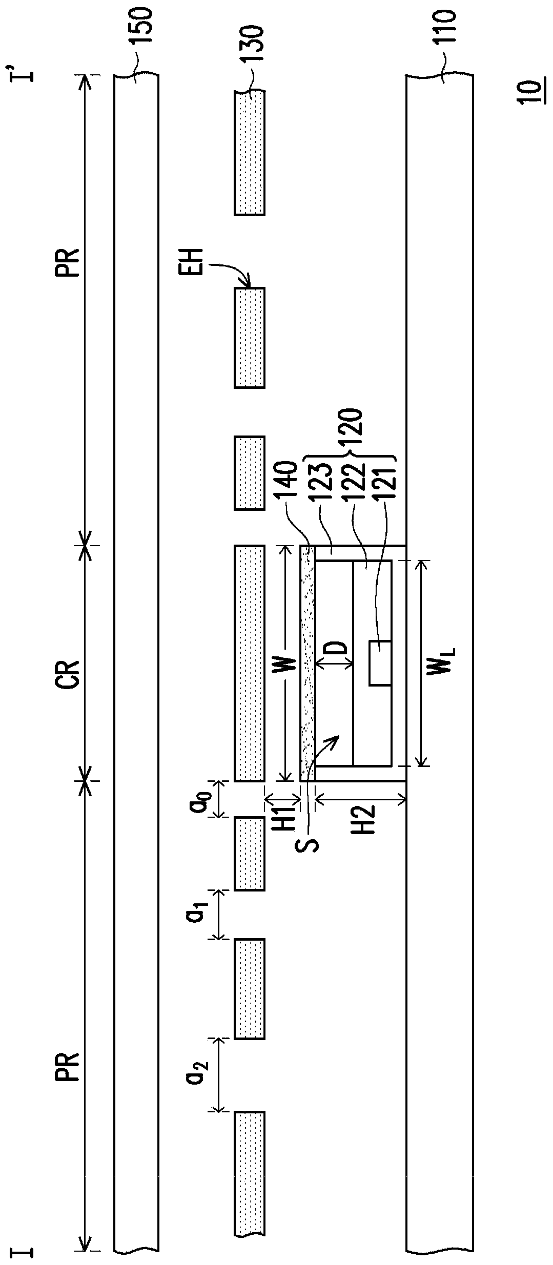
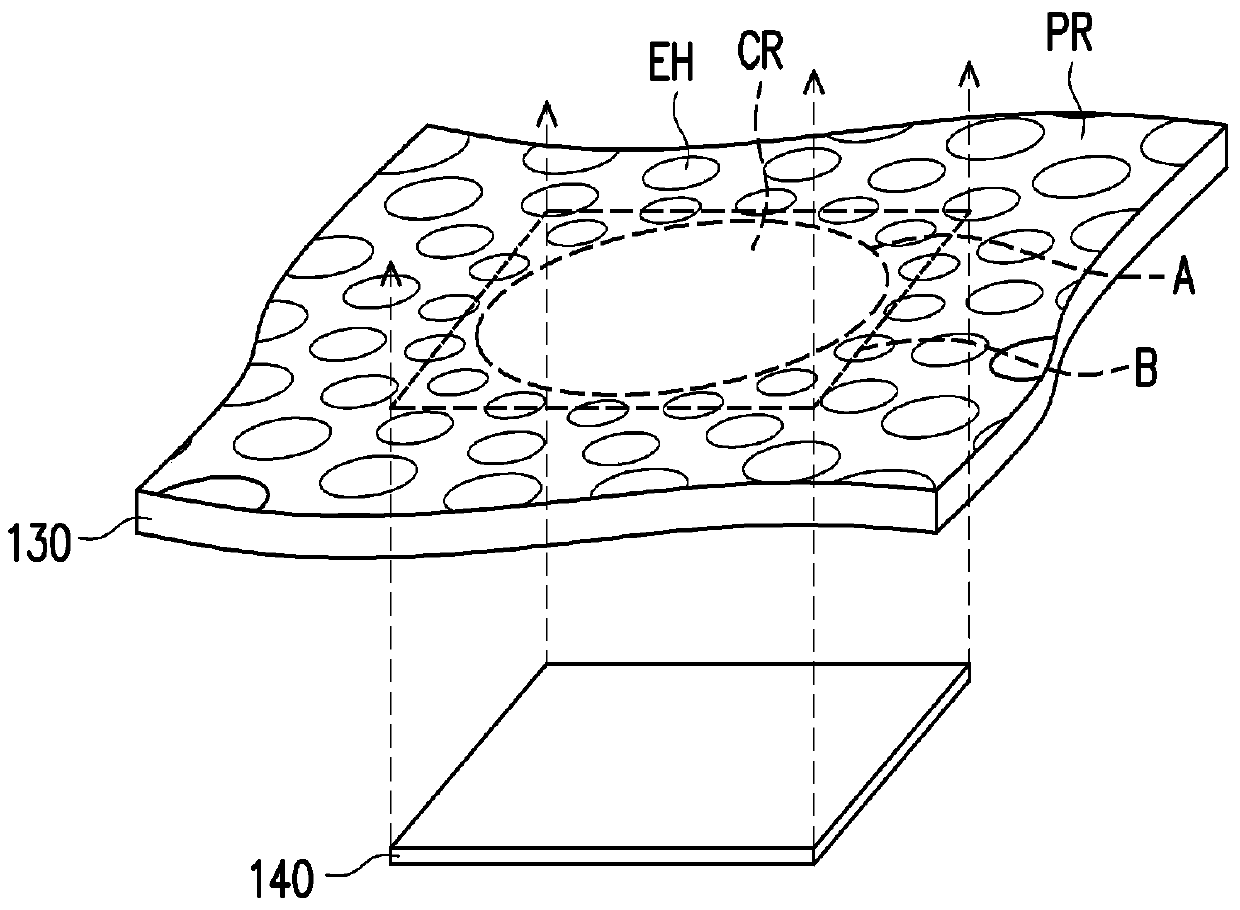
[0064] figure 1 is an exploded schematic diagram of a light source module according to an embodiment of the present invention. Figure 2A for figure 1 The schematic cross-sectional view of the light source module along the section line I-I'. Figure 2B for figure 1 Exploded schematic diagram of the porous optical film and the wavelength conversion optical layer of the light source module. Please also refer to figure 1 as well as Figure 2A , the backlight module 10 of this embodiment includes a substrate 110 , a light source 120 , a wavelength conversion optical layer 130 and a porous optical film 140 , wherein the backlight module 10 may further include a diffusion film 150 . In this embodiment, a single light source 120 is taken as an example to describe the relative positional relationship of the above-mentioned components. Above, the detailed structure of the light source matrix LM will be explained in the following paragraphs. In addition, the backlight module 10 a...


PUM

PropertyMeasurementUnit
refractive indexaaaaaaaaaa

Abstract

A backlight module including a substrate, a light source, a porous optical film, and a wavelength conversion optical layer is provided. The light source is located on the substrate. The porous optical film is disposed over the light source and has a plurality of emission structures, and the porous optical film distributes light generated by the light source to be emitted through the emission structures located at different positions of the porous optical film. The porous optical film has a central region and a peripheral region surrounding the central region, the central region is disposed corresponding to the light source, and an area of the central portion is A. The wavelength conversion optical layer is located between the light source and the porous optical film, and a vertical projection area of the wavelength conversion optical film is B, where 0.49≤A / B≤5.

Description

technical field [0001] The invention relates to a backlight module, and in particular to a backlight module with better brightness uniformity. Background technique [0002] A liquid crystal display device generally includes a liquid crystal display panel and a light source module, wherein the light source module is mainly used to provide a surface light source required by the liquid crystal display panel for displaying. Generally speaking, the light source modules can be classified into direct type and edge-lit type according to the position of the light source. The light source of the direct light source module is arranged directly below the light source module, and is usually used for larger-sized liquid crystal displays, while the light source of the side-light light source module is arranged on the side of the light source module, and is usually used for smaller-sized liquid crystal displays . [0003] In order to prevent uneven brightness of the liquid crystal display...

Claims


Application Information

Patent Timeline
Patent Type & Authority Patents(China)
IPC IPC(8): G02F1/13357
CPCG02F1/133606G02F1/133611G02F1/133603G02F2202/36G02F1/133614
Inventor 彭冠杰陈明伦徐明君王致凯陈重廷王明政
Owner AU OPTRONICS CORP
Features
  • R&D
  • Intellectual Property
  • Life Sciences
  • Materials
  • Tech Scout
  • Unparalleled Data Quality
  • Higher Quality Content
  • 60% Fewer Hallucinations
Learn More