
Machine state recognition method based on oil monitoring technology

A technology for oil monitoring and machine status, applied in character and pattern recognition, instruments, computer parts, etc., can solve problems such as inability to accurately realize clustering and identification of wear monitoring data

Active Publication Date: 2019-04-19
XIAN TECH UNIV
View PDF4 Cites 0 Cited by
  • Summary
  • Abstract
  • Description
  • Claims
  • Application Information

AI Technical Summary

Problems solved by technology

[0007] The purpose of the present invention is to provide a machine state recognition method based on oil monitoring technology, by performing heavy-load accelerated wear tests on cylinder liners / piston rings on a pin-on-disc wear tester, simulating the constantly changing load and speed of the engine In real working conditions, OLVF is used to reflect the changes in the concentration of abrasive particles in the lubricating oil in real time, which solves the technical problem that the previous methods cannot accurately realize the cluster identification of wear monitoring data

Method used


Image

  • Machine state recognition method based on oil monitoring technology
  • Machine state recognition method based on oil monitoring technology
  • Machine state recognition method based on oil monitoring technology

Examples


Embodiment

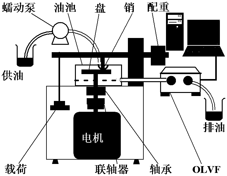
[0147] The wear test was carried out by using a self-made pin-on-disc wear tester. A peristaltic pump is used to supply oil to the friction pair, and OLVF is used to periodically collect lubricating oil samples in the wear oil pool to obtain information on the concentration of abrasive particles in the lubricating oil. The schematic diagram of the test system is as follows: figure 2 shown. The upper sample used in the test is the first air ring of an engine cut into several small sections, and its outer surface is chrome-plated. The sample on the piston ring is clamped on the fixture. The lower test plate used in the test is a gray cast iron plate with a diameter of 60 mm and a thickness of 5 mm. The material is HT250 and the hardness is HV210. The material used for the test disc is close to the real material of the engine.

[0148] The OLVF system is used to monitor the concentration of ferromagnetic abrasive particles in the lubricating oil online, and the IPCA value of ...

Embodiment 2

[0164] Example 2: Working condition identification of the engine tribology system

[0165] When the engine works under variable working conditions, the working conditions of typical friction pairs are also changing constantly. Therefore, the cluster analysis method for friction pairs mentioned above is used for the cluster analysis of the working conditions of the OLVF monitoring data of the whole engine.

[0166] Engine bench test and data processing:

[0167] 1) Bench test data

[0168] A four-cylinder gasoline engine was selected for the test, and the thermal shock test was carried out after the running-in process. The OLVF monitoring system was used to monitor the engine wear state. Among them, about 104 hours of engine wear monitoring data are analyzed (such as Figure 7 shown).

[0169] 2) Dynamic sliding window data segmentation

[0170] During the online monitoring process, the sliding window model is periodically updated to segment the continuously collected OLVF ...


PUM


Abstract

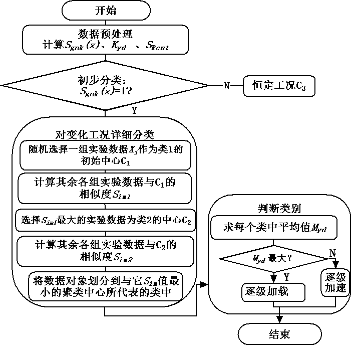
The invention relates to a machine state recognition method based on oil monitoring technology. Most of the existing methods are based on off-line monitoring methods, which are not suitable for on-line monitoring. The state classification is rigid, and it is not combined with the time-varying characteristics of the abrasive particle concentration, so it cannot achieve the purpose of efficient classification and state identification. The present invention preprocesses test data in sections and extracts relative wear characteristic values; conducts preliminary identification of constant working conditions and time-varying working conditions according to the change trend of wear characteristic values; further extracts amplitude characteristic quantities and Slope difference information entropy, constructing a comprehensive weighted similarity model suitable for OLVF; performing secondary clustering on test data under time-varying working conditions, and judging the current working condition type and wear degree in real time. The invention realizes preliminary identification of time-varying working conditions and constant working conditions, constructs an OLVF monitoring similarity evaluation model CWSIM, can accurately measure the real relationship between irregular OLVF monitoring data, and has a high accuracy rate of working condition classification.

Description

technical field [0001] The invention belongs to the interdisciplinary technical field of tribology and fault diagnosis, and in particular relates to a machine state recognition method based on oil monitoring technology. Background technique [0002] Cylinder liner / piston ring friction pair is one of the most critical friction pairs of automobile engine, and the research on its wear problem has always been the focus of scholars from all over the world. [0003] Many scholars at home and abroad have conducted a lot of research on the wear state of cylinder liner / piston ring under laboratory conditions. Representative ones are: Combining theory and experiment, a wear model based on Archard's law is proposed to analyze the wear problem of the cylinder liner / piston ring system. Or the friction and wear behavior of the cylinder liner / piston ring friction pair under different working conditions was studied under laboratory conditions, and it was found that the wear rate of the cyl...

Claims


Application Information

Patent Timeline
Patent Type & Authority Patents(China)
IPC IPC(8): G06K9/62
CPCG06F18/232G06F18/24137
Inventor 曹蔚张洋李军宁董光能陈渭谢友柏
Owner XIAN TECH UNIV
Learn More