Mouse trap

A mousetrap and mouse technology, applied in the field of mousetrap, can solve the problems of large power consumption of mousetrap circuit, high cost of mousetrap, unfavorable energy saving, etc., and achieve the effect of easy collection and use, and energy saving

Inactive Publication Date: 2016-08-17
梁芮涵
View PDF9 Cites 3 Cited by
  • Summary
  • Abstract
  • Description
  • Claims
  • Application Information

AI Technical Summary

Problems solved by technology

[0002] Mouse is a kind of animal that has a relatively large impact on people's production and life. In the prior art, there are quite a lot of types of mousetrap, such as mousetrap, mousetrap, box-type mousetrap, photoelectric mousetrap and sticky mouse trap. glue, etc., although there are many types of mousetrap, some of which can realize continuous mouse catching, but the power consumption of the mouse catching circuit is relatively large, and the cost of catching mice is relatively high, which is not conducive to saving energy; some cannot realize continuous mouse catching; Cannot provide clean energy for self-use

Method used


Image

  • Mouse trap
  • Mouse trap
  • Mouse trap

Examples


Embodiment 1

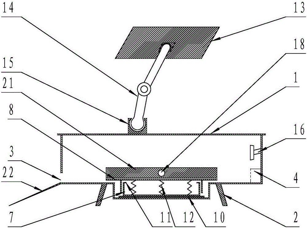
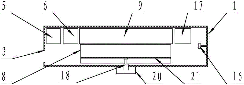
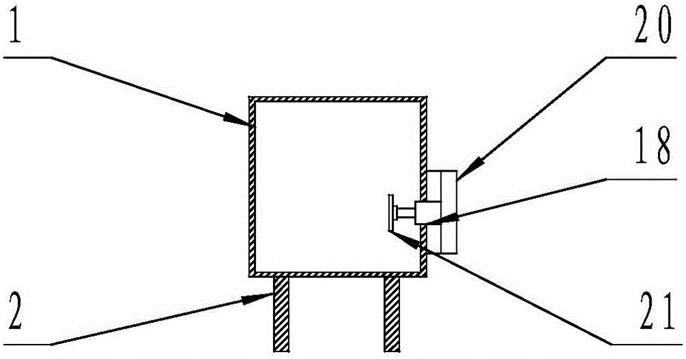
[0020] Such as figure 1 , figure 2 , image 3 As shown, a mousetrap includes a mousetrap box 1, and the mousetrap box 1 is surrounded by a top wall, a bottom wall, two front and rear side walls, and two left and right side walls (usually considered : The length of the mousetrap box is longer than the width and the side wall facing people is the front side wall, the side wall away from people is the rear side wall, the left side of people is the left side wall of the mousetrap box, people The right side of the mousetrap box is the right side wall of the mousetrap box), and the front and rear sides of the bottom surface of the bottom wall of the mousetrap box 1 are respectively provided with two supporting legs 2 in sequence, and the left side of the mousetrap box 1 The side wall is provided with a mouse passage entrance 3, and a mouse bait box 4 is arranged on a position close to the inner wall of the right side wall of the mousetrap box 1 in the mousetrap box 1, and it is c...

Embodiment 2

[0025] Such as figure 1 , figure 2 , image 3 As shown, a mousetrap includes a mousetrap box 1, and the mousetrap box 1 is surrounded by a top wall, a bottom wall, two front and rear side walls, and two left and right side walls (usually considered : The length of the mousetrap box is longer than the width and the side wall facing people is the front side wall, the side wall away from people is the rear side wall, the left side of people is the left side wall of the mousetrap box, people The right side of the mousetrap box is the right side wall of the mousetrap box), and the front and rear sides of the bottom surface of the bottom wall of the mousetrap box 1 are respectively provided with two supporting legs 2 in sequence, and the left side of the mousetrap box 1 The side wall is provided with a mouse passage entrance 3, and a mouse bait box 4 is arranged on a position close to the inner wall of the right side wall of the mousetrap box 1 in the mousetrap box 1, and it is c...


PUM


Abstract

The invention discloses a mouse trap used for catching mice. The mouse trap comprises a mouse trap box, a downwards recessed part is formed in the bottom wall between two supporting legs of the mouse trap box, a mouse trap device is mounted at the downwards recessed part of the bottom wall in the mouse trap box, and the mouse trap further comprises an electric shock mouse pushing device and a solar power supply device for supplying power energy to the mouse trap device and the electric shock mouse pushing device. Continuous mouse catching is realized; self-use clean energy is further provided, the purposes of energy saving and environmental protection are achieved, the defects of higher power consumption and higher voltage of mouse trap circuits of existing mouse traps and higher mouse trap energy consumption are overcome, and the energy saving purpose is achieved.

Description

technical field [0001] The invention belongs to a mousetrap, in particular to a solar continuous mousetrap. Background technique [0002] Mouse is a kind of animal that has a relatively large impact on people's production and life. In the prior art, there are quite a lot of types of mousetrap, such as mousetrap, mousetrap, box-type mousetrap, photoelectric mousetrap and sticky mouse trap. glue, etc., although there are many types of mousetrap, some of which can realize continuous mouse catching, but the power consumption of the mouse catching circuit is relatively large, and the cost of catching mice is relatively high, which is not conducive to saving energy; some cannot realize continuous mouse catching; Can not provide self-use clean energy. How to prepare a mousetrap that can provide clean energy for self-use, realize energy saving and environmental protection, save energy, and realize continuous mouse trapping is a problem that needs to be solved. Contents of the inv...

Claims


Application Information

Patent Timeline
Patent Type & Authority Applications(China)
IPC IPC(8): A01M23/16
CPCA01M23/16
Inventor 梁芮涵
Owner 梁芮涵
Why Eureka
Try Eureka