Eureka AIR delivers breakthrough ideas for toughest innovation challenges, trusted by R&D personnel around the world.

Dummy shaft U-bolt tightening machine

A technology of tightening machine and dummy shaft, which is applied in metal processing, metal processing equipment, manufacturing tools, etc., can solve problems such as the breakage of extension rods, potential safety hazards, and increased investment in equipment costs, and achieve the effect of avoiding potential safety hazards

Active Publication Date: 2017-09-29
ANHUI JIANGHUAI AUTOMOBILE GRP CORP LTD
View PDF5 Cites 0 Cited by
  • Summary
  • Abstract
  • Description
  • Claims
  • Application Information

AI Technical Summary

Problems solved by technology

[0004] However, due to on-site environmental constraints and inconsistent heights of various models, the tightening machine will use extension rods during use, and there is a risk of breaking the extension rods during long-term use. Large vibration, which aggravates the risk of breaking the extension rod; for a double-spindle tightening machine, if one of the tightening shafts is twisted during the tightening process, all the force of the tightening machine will be applied to the other tightening shaft. At the same time, the tightening machine rotates around the other tightening shaft, which has caused a great safety hazard; for the four-axis tightening machine, although one tightening shaft is broken, it can still maintain stability, but compared with the double-axis tightening machine, the increased The two tightening shafts also increase the investment in equipment costs

Method used


Image

  • Dummy shaft U-bolt tightening machine
  • Dummy shaft U-bolt tightening machine
  • Dummy shaft U-bolt tightening machine

Examples


Embodiment Construction

[0034] Embodiments of the present invention are described in detail below, examples of which are shown in the drawings, wherein the same or similar reference numerals designate the same or similar elements or elements having the same or similar functions throughout. The embodiments described below by referring to the figures are exemplary only for explaining the present invention and should not be construed as limiting the present invention.

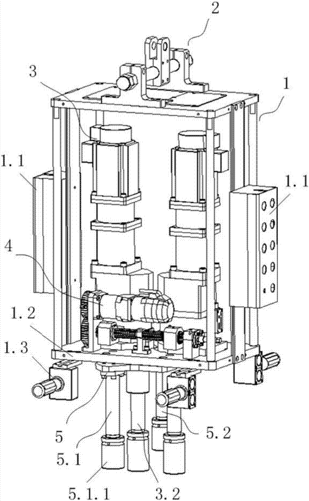
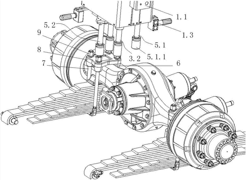
[0035] figure 1 The schematic diagram of the structure of the dummy shaft U-shaped bolt tightening machine provided by the embodiment of the present invention, figure 2 The state diagram of the application of the pseudo-axis U-shaped bolt tightening machine provided by the embodiment of the present invention to actual work.

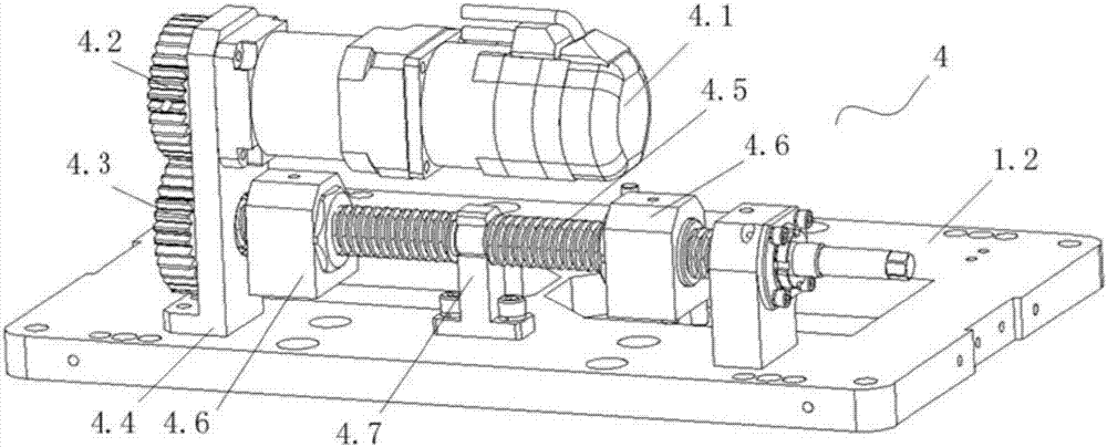
[0036] Please also refer to figure 1 and figure 2 , the embodiment of the present invention provides a dummy shaft U-shaped bolt tightening machine, including a body 1, a suspension device 2, a tightening shaft...


PUM


Abstract

The invention discloses a false-shaft U-shaped bolt tightening machine which comprises a machine body. The false-shaft U-shaped bolt tightening machine further comprises a tightening shaft module arranged on a bottom plate of the machine body, and a false shaft module, wherein the tightening shaft module comprises two tightening shafts and a motor; the motor is used for driving the tightening shafts to rotate; the tightening shafts and the motor are fixedly arranged on the bottom plate; a set distance is formed between the two tightening shafts; the false shaft module is fixedly arranged on the bottom plate and comprises a first false shaft and a second false shaft; the first false shaft and the second false shaft are respectively arranged on two sides of the tightening shafts. According to the false-shaft U-shaped bolt tightening machine provided by the invention, the false shafts are respectively arranged on two sides of the tightening shafts, and reactive force is provided, so that the tightening machine also can be kept stable under the condition that the tightening shafts are broken, and the risk that the tightening machine is out of control in the operating process due to breakage of the tightening shafts as well as potential safety hazards caused by same are avoided.

Description

technical field [0001] The invention relates to a tightening tool, in particular to a dummy shaft U-shaped bolt tightening machine. Background technique [0002] At present, the tightening operation in the assembly workshop is mainly realized by pneumatic tools, battery guns, torque wrenches and tightening machines. In the actual production on site, screwing machines are generally used for the key processes of high torque to ensure the quality. [0003] Existing tightening machines are generally divided into two-axis tightening machines and four-axis tightening machines. The tightening shafts on the tightening machine correspond to the ends of one or more sets of U-shaped bolts respectively, and the synchronous tightening of each end is realized through motor drive. [0004] However, due to on-site environmental constraints and inconsistent heights of various models, the tightening machine will use extension rods during use, and there is a risk of breaking the extension rod...

Claims


Application Information

Patent Timeline
Patent Type & Authority Patents(China)
IPC IPC(8): B23P19/06
CPCB23P19/069
Inventor 夏林生彭海峰洪翎
Owner ANHUI JIANGHUAI AUTOMOBILE GRP CORP LTD
Why Eureka
Eureka Blog
Learn More