
A Two-degree-of-Freedom Rotational Parallel Mechanism Existing Two Continuous Rotation Axes

A technology of rotation axis and degree of freedom, applied in the field of robotics, can solve the problems of difficult processing and manufacturing, large number of single-degree-of-freedom motion pairs, and low overall rigidity, achieving small number, easy kinematic calibration and control, and high overall rigidity of the mechanism Effect

Active Publication Date: 2018-01-23
YANSHAN UNIV
View PDF7 Cites 0 Cited by
  • Summary
  • Abstract
  • Description
  • Claims
  • Application Information

AI Technical Summary

Problems solved by technology

The two-degree-of-freedom rotating parallel mechanism includes a two-degree-of-freedom spherical mechanism and a two-degree-of-freedom rotating parallel mechanism without a meeting point. The two rotational axes of the two-degree-of-freedom spherical parallel mechanism are continuous, but it must meet the requirements that the axis of the rotating pair meet at a certain point. It is very difficult to process and manufacture the geometric requirements of points; and there are not many existing two-degree-of-freedom parallel mechanisms without converging points that have two continuous shafts, and most of them have a constrained branch that only includes Hooke hinges, such as Chinese patent CN200710061909 .8 The proposed mechanism, etc., and contains a large number of single-degree-of-freedom motion pairs, and the overall stiffness is low

Method used


Image

  • A Two-degree-of-Freedom Rotational Parallel Mechanism Existing Two Continuous Rotation Axes

Examples


Embodiment Construction

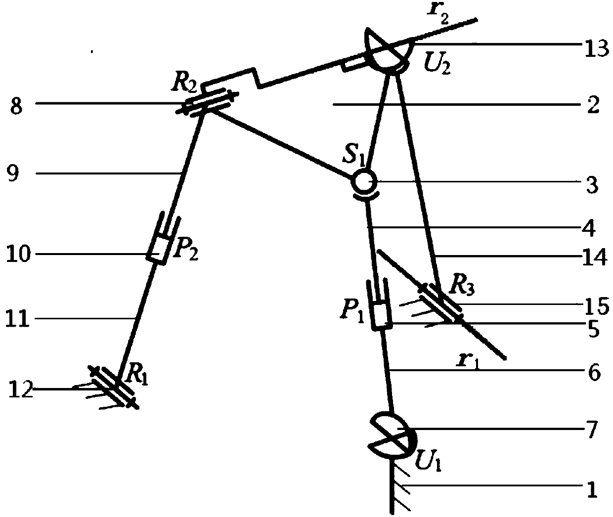
[0008] exist figure 1 In the schematic diagram of the two-degree-of-freedom rotating parallel mechanism with two continuous rotation axes shown, three branch chains connect the fixed platform 1 and the moving platform 2, and one end of the upper link 4 of the first branch chain is connected to the moving platform through the ball pair 3 , the other end of the upper link is connected with one end of the lower link 6 through the moving pair 5, and the other end of the lower link is connected with the fixed platform through the Hooke hinge 7; one end of the upper link 9 of the second branch is passed The rotating pair 8 is connected with the moving platform, the other end of the upper connecting rod is connected with one end of the lower connecting rod 11 through the moving pair 10, and the other end of the lower connecting rod is connected with the fixed platform through the rotating pair 12; One end of the rod 14 is connected with the moving platform through the Hooke hinge 13,...


PUM


Abstract

A two-degree-of-freedom rotational parallel mechanism with two continuous rotating axes comprises a fixed platform, a movable platform, and three branch chains which can connect the fixed platform with the movable platform, wherein the first branch chain and the second branch chain are both composed of upper connecting rods and lower connecting rods; the upper connecting rod and the lower connecting rod of the first branch chain are correspondingly connected to the movable platform and the fixed platform through a ball pair and a hook joint; the upper connecting rod and the lower connecting rod of the second branch chain are both connected to the movable platform and the fixed platform through a rotating pair; the upper connecting rods and the lower connecting rods of the two branch chains are connected through moving pairs; two ends of a connecting rod of a third branch chain are correspondingly connected to the movable platform and the fixed platform through the hook joint and the rotating pair; an axis of the rotating pair, connected to the movable platform, of the second branch chain, is overlapped with the axis of the rotating pair, connected to the movable platform through the hook joint, of the third branch chain; the axis of the rotating pair, connected to the fixed platform, of the second branch chain, is parallel to the axis of the rotating pair of the third branch chain. According to the mechanism, the two continuous rotating axes are provided, so that the kinematics calibration and control are easily achieved; in addition, few single-degree-of-freedom moving pairs are provided, so that the rigidity of the whole mechanism is high.

Description

technical field [0001] The invention belongs to the field of robots, in particular to a parallel mechanism. Background technique [0002] The two-degree-of-freedom rotary parallel mechanism is an important branch of the few-degree-of-freedom parallel mechanism. It is used in many occasions, such as attitude adjustment and self-stabilization of platforms on ships, vehicles and aircraft, positioning of medical equipment, cameras and telescopes, and antennas and solar panels. Fields such as azimuth tracking have great application prospects. The two-degree-of-freedom rotating parallel mechanism includes a two-degree-of-freedom spherical mechanism and a two-degree-of-freedom rotating parallel mechanism without a meeting point. The two rotational axes of the two-degree-of-freedom spherical parallel mechanism are continuous, but it must satisfy that the axis of the rotating pair meets at a certain point. It is very difficult to process and manufacture due to the geometric requirem...

Claims


Application Information

Patent Timeline
Patent Type & Authority Patents(China)
IPC IPC(8): B25J9/00
CPCB25J9/0072
Inventor 许允斗王贝闫文楠陈亮亮刘文兰张东胜赵永生
Owner YANSHAN UNIV
Learn More