Rotational structure of mechanical arm for automatic lathe

A technology of mechanical arm and rotating structure, applied in the direction of manipulator, program-controlled manipulator, injection device, etc., can solve the problems of easy fatigue, waste of manpower, easy to soil hands, etc., and achieve high economic benefits, manpower saving, and easy operation. Effect

Inactive Publication Date: 2016-08-17
韩永亮
View PDF8 Cites 1 Cited by
  • Summary
  • Abstract
  • Description
  • Claims
  • Application Information

AI Technical Summary

Problems solved by technology

[0002] In the process of producing electric hoists, it is usually necessary to spray paint, trim, and transfer the end caps of the electric hoist. Now the operation methods for these processes are all realized by manual operation. For the electric hoist accessories that have just been painted , the spray paint on the outer surface is not dry, it is easy to dirty hands during manual operation, and for the parts that have just been welded, the heat of the body has not been completely dissipated, and it is easy to cause the danger of burns to the operator. The operation of the process is a waste of manpower, and the operator is prone to fatigue when performing the above operations for a long time, which affects work efficiency and even the economic benefits of the marketing company; in summary, a mechanical device that replaces manual operation is needed to realize electric hoist accessories. During the transfer work, it is necessary to adjust the rotation and positioning of the electric hoist accessories during the transfer process

Method used


Image

  • Rotational structure of mechanical arm for automatic lathe
  • Rotational structure of mechanical arm for automatic lathe
  • Rotational structure of mechanical arm for automatic lathe

Examples


Embodiment 1

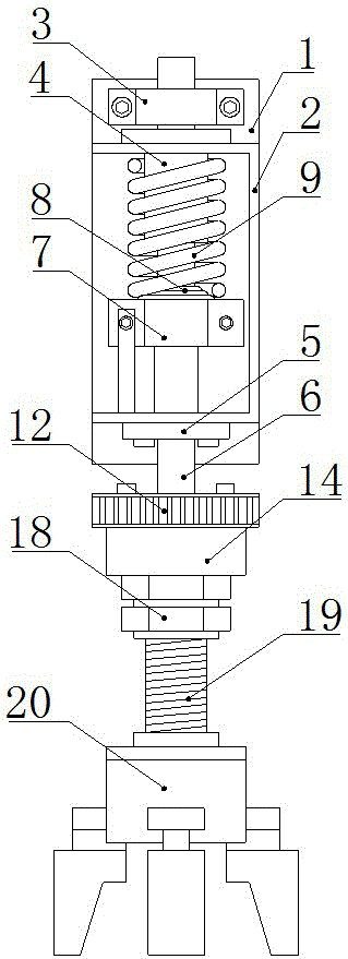
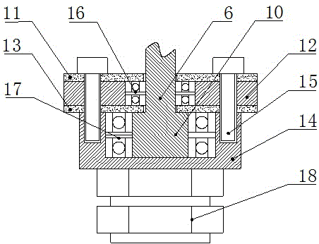
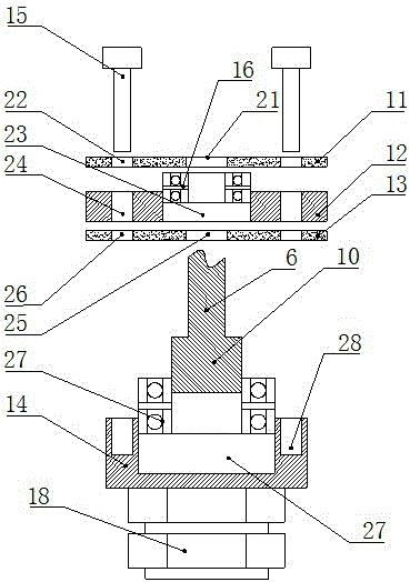
[0018] Such as Figure 1-3 Shown, the rotating structure of the mechanical arm of a kind of automatic lathe, it comprises fixed plate A1 and the fixed plate B2 that is welded on the fixed plate A1, the upper part of described fixed plate A1 is fixed with bearing block 3 by hexagonal bolt, described The upper end of the fixed plate B2 is fixed with a linear bearing A4, the lower end of the fixed plate B2 is fixed with a linear bearing B5, the linear bearing A4 and the linear bearing B5 pass through a rotating shaft 6, and one end of the rotating shaft 6 passes through the bearing seat 3. The upper side of the lower end of the fixed plate B2 is fixed with a fixed shaft block 7 through a hexagonal bolt, and a rubber gasket 8 is arranged between the fixed shaft block 7 and the linear bearing A4, and a buffer spring is arranged on the outer circumference of the linear bearing A4 9. The lower end of the rotating shaft 6 is provided with a protrusion 10, and the lower part of the rot...

Embodiment 2

[0021] Such as Figure 1-3 Shown, the rotating structure of the mechanical arm of a kind of automatic lathe, it comprises fixed plate A1 and the fixed plate B2 that is welded on the fixed plate A1, the upper part of described fixed plate A1 is fixed with bearing block 3 by hexagonal bolt, described The upper end of the fixed plate B2 is fixed with a linear bearing A4, the lower end of the fixed plate B2 is fixed with a linear bearing B5, the linear bearing A4 and the linear bearing B5 pass through a rotating shaft 6, and one end of the rotating shaft 6 passes through the bearing seat 3. The upper side of the lower end of the fixed plate B2 is fixed with a fixed shaft block 7 through a hexagonal bolt, and a rubber gasket 8 is arranged between the fixed shaft block 7 and the linear bearing A4, and a buffer spring is arranged on the outer circumference of the linear bearing A4 9. The lower end of the rotating shaft 6 is provided with a protrusion 10, and the lower part of the rot...


PUM


Abstract

The invention relates to a rotational structure of a mechanical arm for an automatic lathe. The rotational structure comprises a fixing plate A and a fixing plate B. A bearing pedestal is fixed to the upper portion of the fixing plate A. A linear bearing A is fixed to the upper end of the fixing plate B, a linear bearing B is fixed to the lower end of the fixing plate B, and a rotating shaft penetrates through the linear bearing A and the linear bearing B. A fixing shaft block is fixed to the upper side of the lower end of the fixing plate B, a rubber gasket is arranged between the fixing shaft block and the linear bearing A, and a buffer spring is arranged on the outer circumference of the linear bearing A. A protrusion part is arranged at the lower end of the rotating shaft. A rotating part is arranged on the lower portion and the protrusion part of the rotating shaft. The rotating part comprises a fixing piece A, a fixing disk, a fixing piece B, a fixing groove and a bolt. A bearing A is arranged inside the fixing disk, and a bearing B is arranged in the fixing groove. Two nuts are fixed to the lower end of the fixing groove. The nuts are connected with a threaded pipe, and a grabbing part is welded to the lower end of the threaded pipe. The rotational structure of the mechanical arm for the automatic lathe has the advantages of being easy and convenient to operate, capable of saving manpower and high in economic benefit.

Description

technical field [0001] The invention relates to a rotating structure, which belongs to the field of automatic mechanical equipment, in particular to a rotating structure of a mechanical arm of an automatic lathe. Background technique [0002] In the process of producing electric hoists, it is usually necessary to spray paint, trim, and transfer the end caps of the electric hoist. Now the operation methods for these processes are all realized by manual operation. For the electric hoist accessories that have just been painted , the spray paint on the outer surface is not dry, it is easy to dirty hands during manual operation, and for the parts that have just been welded, the heat of the body has not been completely dissipated, and it is easy to cause the danger of burns to the operator. The operation of the process is a waste of manpower, and the operator is prone to fatigue when performing the above operations for a long time, which affects work efficiency and even the econom...

Claims


Application Information

Patent Timeline
Patent Type & Authority Applications(China)
IPC IPC(8): B25J9/04B05B13/04
CPCB05B13/0431B25J9/04
Inventor 韩永亮
Owner 韩永亮
Why Eureka
Try Eureka