
Arc plastic plate grooving mechanism

A plastic plate and grooving technology, applied in metal processing and other directions, can solve the problems of affecting the processing effect, troublesome clamping, deformation of the curved plastic plate, etc., and achieve the effect of improving the processing effect and simplifying the processing.

Active Publication Date: 2016-08-17
佛山市顺德区金业华橡塑有限公司
View PDF6 Cites 26 Cited by
  • Summary
  • Abstract
  • Description
  • Claims
  • Application Information

AI Technical Summary

Problems solved by technology

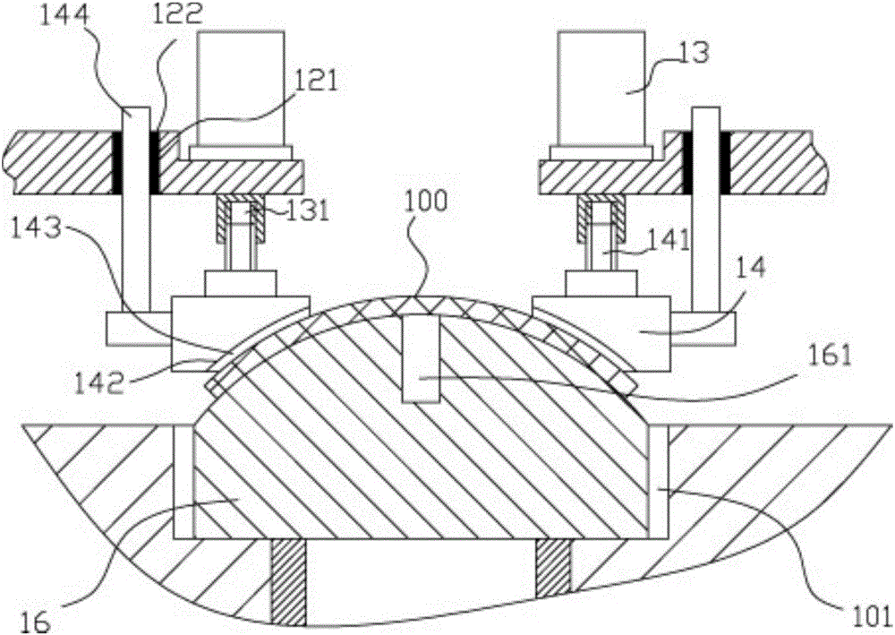
[0002] When the existing arc-shaped plastic plate is cut and processed, it needs to be fixed. The existing fixing method is to manually fix the edge of the arc-shaped plastic plate with a pressure block or to set the edge of the arc-shaped plastic plate in advance. The process hole is fixed on the table through the process hole for cutting. It is troublesome to clamp, and because the middle part of the arc-shaped plastic plate is arc-shaped, when the positioning is fixed, the bottom of the arc-shaped plastic plate has no support block, which makes cutting easy. Deform the curved plastic plate and affect the processing effect

Method used


Image

  • Arc plastic plate grooving mechanism
  • Arc plastic plate grooving mechanism
  • Arc plastic plate grooving mechanism

Examples


Embodiment

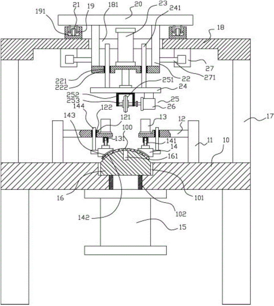
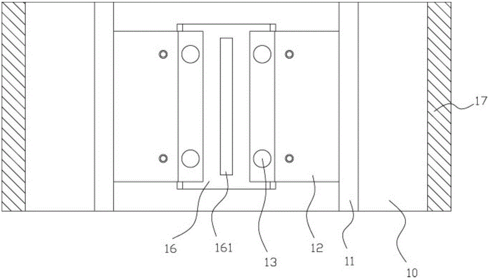
[0019] Example: see Figure 1 to Figure 3 As shown, an arc-shaped plastic plate grooving mechanism includes a frame 10, the top plate of the frame 10 is fixed with vertical plates 17 on both sides, and the bottom ends of the upper support plate 18 are fixed on two vertical plates. On the top surface of 17, the middle part of the upper support plate 18 has a moving through groove 181, the top surface of the upper support plate 18 on both sides of the moving through groove 181 is fixed with sliding grooves 19, and the bottom surfaces of both ends of the upper moving block 20 are provided with multiple A supporting roller 21 is inserted into the sliding groove 191 on the top surface of the sliding groove body 19, a lower connecting frame 22 is fixed on the bottom surface of the upper moving block 20, and the lower connecting frame 22 is inserted and sleeved in the moving through groove 181 , The lower end of the lower connecting frame 22 extends downwards from the moving through s...


PUM


Abstract

The invention discloses an arc plastic plate grooving mechanism which comprises a rack, wherein vertical plates are fixed on the two sides of a top plate of the rack; the two ends of the bottom surface of an upper support plate are fixed on the top surfaces of the two vertical plates; a moving through groove is formed at the middle part of the upper support plate; sliding groove bodies are fixed in the top surfaces of the upper support plates on the two sides of the moving through groove; multiple support rollers are arranged on the two end bottom surfaces of an upper moving block; the support rollers are inserted in the sliding groove in the top surface of the sliding groove body in a sleeving manner; a lower connection frame is fixed on the bottom surface of the upper moving block and inserted in the moving through groove in a sleeving manner; the lower end of the lower connection frame extends out of the moving through groove; a position adjusting air cylinder is fixed on the top surface of the bottom plate of the lower connection frame; the end part of a push rod of the position adjusting air cylinder goes through the bottom plate of the lower connection frame, and a connection plate body is fixed at the end part; and a cutting mechanism is arranged on the bottom surface of the connection plate body. An arc plastic plate can be automatically clamped, fixed and cut; and the arc plastic plate is supported by the bottom support block and prevented from deformation, and thus the processing effect is improved.

Description

Technical field: [0001] The invention relates to the technical field of plastic processing equipment, and more specifically to an arc-shaped plastic plate grooving mechanism. Background technique: [0002] When the existing curved plastic board is cut, it needs to be fixed. The existing fixing method is to manually fix the edge of the curved plastic board with a pressure block or set it on the edge of the curved plastic board in advance. The process hole is fixed on the table through the process hole for cutting, and the clamping is troublesome, and because the middle of the arc plastic plate is arc, and when positioning and fixing, there is no support block at the bottom of the arc plastic plate, making it easy to cut The curved plastic plate is deformed and the processing effect is affected. Summary of the invention: [0003] The purpose of the present invention is to address the shortcomings of the prior art and provide an arc-shaped plastic plate grooving mechanism, which can...

Claims


Application Information

Patent Timeline
IPC IPC(8): B26D1/157B26D7/01B26D7/02
CPCB26D1/157B26D7/01B26D7/02
Inventor 付淑珍
Owner 佛山市顺德区金业华橡塑有限公司
Learn More