Self-cleaning barrel and washing machine employing same

A self-cleaning and washing machine technology, applied in the field of washing machines, can solve problems such as poor self-cleaning effect, and achieve the effect of increasing cleaning frequency and good cleaning effect

Active Publication Date: 2016-08-17
GREE ELECTRIC APPLIANCES INC
View PDF9 Cites 15 Cited by
  • Summary
  • Abstract
  • Description
  • Claims
  • Application Information

AI Technical Summary

Problems solved by technology

[0007] The purpose of the present invention is to propose a self-cleaning cylinder, which can solve the problem of poor self-cleaning effect in the prior art
[0008] Another object of the present invention is to propose a washing machine that can solve the problem of poor self-cleaning effect in the prior art

Method used


Image

  • Self-cleaning barrel and washing machine employing same
  • Self-cleaning barrel and washing machine employing same
  • Self-cleaning barrel and washing machine employing same

Examples


Embodiment approach 1

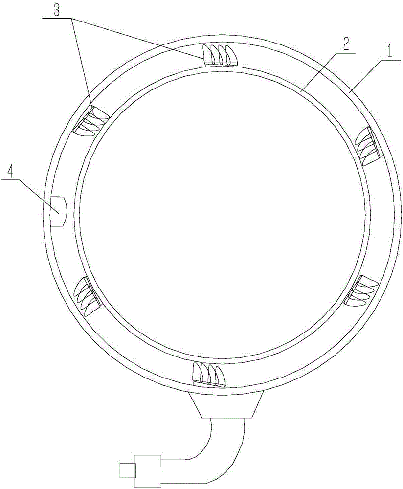
[0037] Such as Figure 1 to Figure 6 As shown, this embodiment provides a self-cleaning cylinder, including an outer cylinder 1, and an inner cylinder 2 sleeved in the outer cylinder 1 and rotatably connected with the outer cylinder 1, wherein the outer cylinder 1 and the inner cylinder 2 A cleaning device 3 is arranged therebetween, and during the relative rotation of the inner cylinder 2 and the outer cylinder 1 , the cleaning device 3 cleans the inner wall of the outer cylinder 1 and the outer wall of the inner cylinder 2 .

[0038] The above-mentioned self-cleaning cylinder is suitable for being installed on a washing machine, especially suitable for being installed on a drum washing machine. By setting the cleaning device 3 between the inner cylinder 2 and the outer cylinder 1, during the working process of the washing machine, the cleaning device 3 will clean the outer wall of the washing machine inner cylinder 2 and the inner wall of the outer cylinder 1, that is, as lo...

Embodiment approach 2

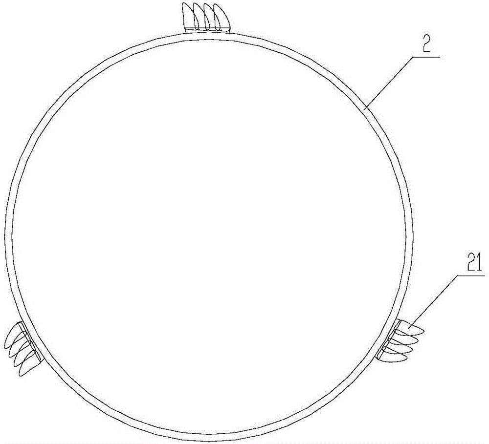
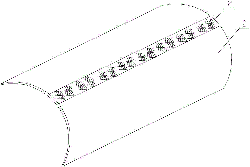
[0050] In this embodiment, another specific installation form of the cleaning device is provided. The cleaning devices 3 provided on the outer cylinder 1 and the cleaning devices 3 provided on the inner cylinder 2 are arranged alternately along the cylinder axis. Specifically as described below, the fixed portion 31 of the cleaning device 3 includes a plurality of fixed portion units arranged at intervals, and the wiping portion 32 includes a plurality of wiper units distributed at intervals, and the wiper units are arranged on the fixed portion in one-to-one correspondence. on the unit.

[0051] Both the outer cylinder 1 and the inner cylinder 2 are provided with a cleaning device 3, the fixed part unit is fixedly connected with the corresponding outer cylinder 1 or inner cylinder 2, and the fixed part unit on the outer cylinder 1 is connected to the fixed part on the inner cylinder 2 The units are arranged in a staggered manner.

[0052] That is, the fixed portion unit of t...

Embodiment approach 3

[0056] In this embodiment, another specific installation form of the cleaning device is provided. Both the outer cylinder 1 and the inner cylinder 2 are provided with groove structures, and the groove structures on the outer cylinder 1 and the inner cylinder 2 are both provided with The cleaning device 3, and the fixed part 31 of the cleaning device 3 is telescopically connected with the corresponding groove structure.

[0057] Concretely, a guide column 35 is arranged at both ends of the groove structure 34 respectively, and the two ends of the fixed part 31 are respectively slidably connected with the two guide columns 35, and a spring 36 is also sleeved on the guide column 35, and one end of the spring 36 is connected to the guide column 35. The fixing portion 31 is in contact with the other end of the groove structure 34 .

[0058] More specifically, the first cleaning device 11 is arranged on the outer cylinder 1 through the cooperation of the guide post 35, the spring 36...


PUM


Abstract

The invention relates to the technical field of washing machines, and in particular relates to a self-cleaning barrel and a washing machine employing the same. The self-cleaning barrel comprises an outer barrel and an inner barrel, wherein the inner barrel is sleeved with the outer barrel and is rotationally connected with the outer barrel; a cleaning device is arranged between the outer barrel and the inner barrel; and the cleaning device is used for cleaning the inner wall of the outer barrel and the outer wall of the inner barrel in the relative rotation process of the inner barrel and the outer barrel. Meanwhile, the invention further provides the washing machine employing the self-cleaning barrel. The cleaning device is arranged between the outer barrel and the inner barrel; the cleaning device is used for cleaning the inner wall of the outer barrel and the outer wall of the inner barrel in the working process of the washing machine, namely self-cleaning can be carried out as long as relative mechanical motion exists in the cleaning process of the barrel; and extra water resource and specific cleaning procedure are not needed, so that the cleaning frequency is greatly improved; and the cleaning effect is good.

Description

technical field [0001] The invention relates to the technical field of washing machines, in particular to a self-cleaning cylinder and a washing machine using the same. Background technique [0002] After a long period of use, a large amount of dirt will remain on the outer wall of the inner cylinder and the inner wall of the outer cylinder of the washing machine, mainly composed of grease, lint, protein, etc. Since the space between the inner cylinder and the outer cylinder is relatively closed, Therefore, it is difficult to clean and easy to breed bacteria, which will eventually cause secondary pollution of clothes and bring hidden dangers to the health of users. [0003] The realization mode of existing washing machine self-cleaning function mainly relies on the modes such as high water level, high temperature, long time washing, and the method for washing clothes is similar. Since no mechanical force is applied to the surface of the inner and outer cylinders, it is diff...

Claims


Application Information

Patent Timeline
Patent Type & Authority Applications(China)
IPC IPC(8): D06F37/02D06F39/00B08B9/087
CPCB08B9/087D06F37/02D06F39/00Y02B40/00
Inventor 温子健
Owner GREE ELECTRIC APPLIANCES INC
Why Eureka
Try Eureka