Box body of miniature speed changing box of bicycle

A technology for gearboxes and bicycles, which is applied to transmission boxes, components with teeth, transmission parts, etc., can solve the problems affecting the reliability of bicycle micro-transmission gearbox parts installation, unreasonable structure, etc., so as to achieve easy installation , Reasonable structure, guarantee the effect of reliable use

Inactive Publication Date: 2016-08-17
石幸运
View PDF7 Cites 0 Cited by
  • Summary
  • Abstract
  • Description
  • Claims
  • Application Information

AI Technical Summary

Problems solved by technology

I have invented some patents related to bicycle center shaft transmissions, such as the title "Bicycle with Miniature Box Transmission on the Center Shaft", the patent number is ZL201010518569.9, and the patent application date is October 25, 2010; Micro box-type transmission", the patent number is ZL201010518578.8, the patent application date is October 25, 2010; the name is "shifting device for bicycle micro-transmission", the patent number is ZL201010518576.9, the patent application date is 2010 On October 25th, the shifting device was in the form of a vertical shaft cam type shifting device; later, on April 15, 2014, it applied for a patent application titled "Slider-type shifting device for a bicycle micro-gearbox". The number is 2014101500245; although the latter improves the effect of bicycle gear shifting, the structure of the box body of the bicycle micro-transmission is not reasonable enough, which seriously affects the reliability of the bicycle micro-transmission and the installation of transmission parts. For this reason, Still to be explored new bicycle micro gearbox case

Method used


Image

  • Box body of miniature speed changing box of bicycle
  • Box body of miniature speed changing box of bicycle
  • Box body of miniature speed changing box of bicycle

Examples


Embodiment

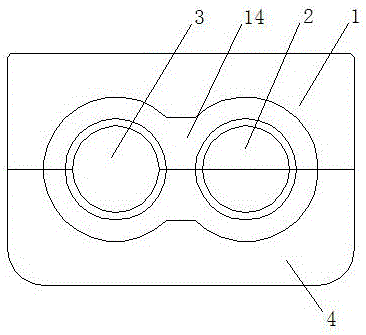
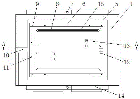
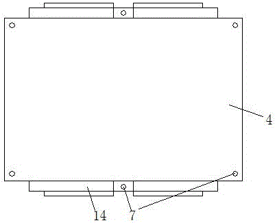
[0016] refer to figure 1 - Fig. 5, a box body of a bicycle micro-transmission box, the upper box body 1 and the lower box body 4 are connected into one body through the box connecting hole 7 with bolts, and the upper box body 1 and the lower box body 4 are integrated to form a pair Shaft hole 2, main shaft hole 3, are provided with shift fork hole 13, slider chute 8, spring groove 15, slider cover plate seat 6, upper cover plate seat 5 on the top of upper box body 1 The center of the upper surface of the front end of the box body 1 is provided with a cable groove 10, bearing blocks 14 are arranged on the left and right sides of the upper box body 1 and the lower box body 4, and a spring positioning hole 11 and a spring cable pulley are arranged in the spring groove 15. The positioning hole 12 is provided with a cover plate connection screw hole 9 on the slider cover plate seat 6 . There are four shift fork holes 13, which are first gear shift fork hole, second gear shift fork...


PUM


Abstract

The box body of the bicycle miniature gearbox of the present invention relates to the box body of a bicycle shaft transmission. A box body of a miniature bicycle gearbox, which is characterized in that the upper box body and the lower box body are connected into one body through the connecting holes of the box body with bolts, and the auxiliary shaft hole and the main shaft hole are formed after the upper box body and the lower box body are integrated. , the top of the upper box is provided with a shift fork hole, a slider chute, a spring groove, a slider cover seat, and an upper cover seat, and a cable groove is provided in the center of the upper surface of the front end of the upper box. The left and right sides of the upper box and the lower box are provided with bearing seats, a spring positioning hole and a spring pulley positioning hole are arranged in the spring groove, and a cover plate connection screw hole is provided on the slider cover plate seat. The box body of the bicycle micro-transmission box of the present invention has reasonable structure, small volume and reliability, and parts are easy to install, which guarantees the reliable use of the bicycle micro-transmission box and has popularization value.

Description

technical field [0001] The invention relates to a box body of a bicycle center shaft transmission, and more particularly relates to a box body of a bicycle miniature gearbox. Background technique [0002] Bicycle, also known as bicycle or bicycle. At present, the speed regulation of bicycles mostly adopts different pairings of chain discs on the central shaft and chainrings on the rear axle for speed regulation, and the transmission speed ratio range is small. I have invented some patents related to bicycle center shaft transmissions, such as the title "Bicycle with Miniature Box Transmission on the Center Shaft", the patent number is ZL201010518569.9, and the patent application date is October 25, 2010; Miniature box-type transmission", the patent number is ZL201010518578.8, the patent application date is October 25, 2010; the name is "shifting device for bicycle micro-transmission", the patent number is ZL201010518576.9, the patent application date is 2010 On October 25t...

Claims


Application Information

Patent Timeline
Patent Type & Authority Applications(China)
IPC IPC(8): F16H57/02
CPCF16H57/02F16H2057/02043
Inventor 石宗泽
Owner 石幸运
Why Eureka
Try Eureka