Continuous armored concrete pavement crack seam test device and method

A technology for reinforced concrete and pavement cracks, which is applied in the direction of measuring devices, mechanical measuring devices, and mechanical devices, etc., can solve the problems of low measurement accuracy, low detection efficiency, and vehicle traffic obstacles, and achieve convenient and flexible operation and testing The effect of high precision and low production cost

Inactive Publication Date: 2016-08-17
CHANGSHA UNIVERSITY OF SCIENCE AND TECHNOLOGY
View PDF7 Cites 7 Cited by
  • Summary
  • Abstract
  • Description
  • Claims
  • Application Information

AI Technical Summary

Problems solved by technology

[0004] (1) The error of manual estimation is large and the detection efficiency is low
The display screen of the crack width gauge shows the result of local enlargement, and the small movement of the measuring probe will cause a large range of movement on the display screen. In actual operation, multiple adjustments are required to make the crack appear on the screen, and Enables cracks to be perpendicular to the fixed scale scale, which leads to inefficient detection
In addition, in the detection, it is necessary to estimate and read the crack width value according to the length of the scale line occupied by the crack image, which leads to low precision of measurement results and large errors;
[0005] (2) Inconvenient operation and great potential safety hazard
When using the crack width gauge, the inspector puts the measuring probe close to the crack on the road surface, and needs to squat on the road surface for a long time. The long-term test in one position not only creates obstacles to the passage of vehicles, but also poses a threat to people who have been looking down for a long time. Testers who screen read data pose a safety hazard

Method used


Image

  • Continuous armored concrete pavement crack seam test device and method
  • Continuous armored concrete pavement crack seam test device and method
  • Continuous armored concrete pavement crack seam test device and method

Examples


Embodiment Construction

[0022] The present invention will be described in further detail below in conjunction with the accompanying drawings.

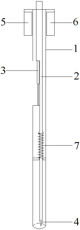
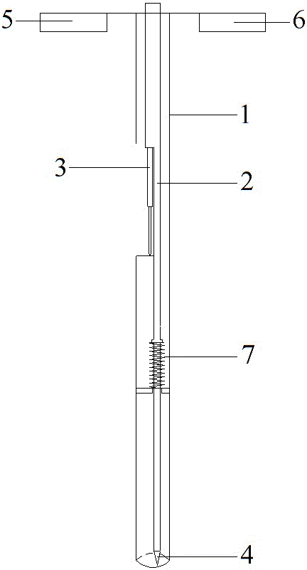
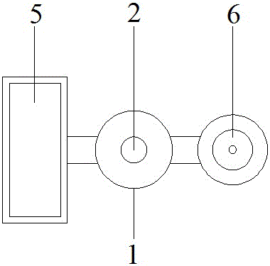
[0023] Such as figure 1 As shown, a device for testing cracks and gaps in continuously reinforced concrete pavement, including an external sleeve (1), a support rod (2), a displacement sensor (3), a conical feeler gauge (4), a display screen (5), a circular The level (6) and spring (7), the conical feeler gauge (4) are connected to the support rod (2); the fixed end of the displacement sensor (3) is connected to the support rod (2); the contact head of the displacement sensor (3) is connected to the outside The positioning surface of the sleeve (1) contacts; the display screen (5) and the circular level (6) are connected with the external sleeve (1).

[0024] The support rod (2) is covered with a spring (7), one end of the spring (7) is constrained by the outer sleeve, and the other end is constrained by the support rod.

[0025] When in use, the display sc...


PUM


Abstract

The invention provides a continuous armored concrete pavement crack seam test device and method. The continuous armored concrete pavement crack seam can be efficiently and fast tested by aiming at the characteristics of the continuous armored concrete pavement. The device consists of an external sleeve, a support rod, a displacement sensor, a conical plug ruler, a display screen, a round spirit level and a spring. The test method comprises the following steps of putting the device above a crack to be detected; unfolding the display screen and the round spirit level to be vertical to the external sleeve; enabling a bubble in the round spirit level to be positioned in the center; aligning the conical plug ruler with the crack seam; pressing down the top end of the support rod; extending the conical plug ruler into the pavement seam; calculating the width of the crack seam through the conical angle extending into the distance and conical plug ruler; outputting the crack seam width data through the display screen. The device and the method have the advantages that the production cost is low; the operation is convenient and flexible; the test precision is high; the efficiency is high; the time and the labor are saved; the popularization is easy.

Description

technical field [0001] The invention belongs to the technical field of road engineering, and relates to a device and a method for testing cracks and gaps of continuously reinforced concrete pavement. Background technique [0002] Continuously reinforced concrete pavement refers to a cement concrete pavement in which longitudinal continuous steel bars and transverse steel bars are arranged in the concrete surface, and there are no or few joints in the horizontal direction. Since there are no or few joints on the continuously reinforced concrete pavement, the drying and temperature shrinkage of the concrete will cause random distribution of transverse cracks on the pavement, and the width of the transverse cracks is usually less than 1mm. For continuously reinforced concrete pavement, the number, spacing and width of transverse cracks are important factors affecting pavement performance. In the detection of concrete structures, the width of surface cracks is an important dete...

Claims


Application Information

Patent Timeline
Patent Type & Authority Applications(China)
IPC IPC(8): G01B5/02E01C23/01
CPCG01B5/02E01C23/01
Inventor 刘朝晖李盛曹前柳力许庆祥李理周梓豪洪岭岭冷静波黄常乐陈尚武
Owner CHANGSHA UNIVERSITY OF SCIENCE AND TECHNOLOGY
Why Eureka
Try Eureka