Distributed optical fiber monitoring calibration and test method and device for soil deformation

A technology of distributed optical fiber and soil deformation, applied in measurement devices, optical devices, instruments, etc., can solve the problems of restricting popularization and application, interaction mechanism between soil and strain sensing fiber, and coordinated deformation problems have not been fully understood , the reliability uncertainty of optical fiber monitoring results, etc.

Active Publication Date: 2016-08-17
NANJING UNIV
View PDF6 Cites 17 Cited by
  • Summary
  • Abstract
  • Description
  • Claims
  • Application Information

AI Technical Summary

Problems solved by technology

This method is relatively convenient for construction, but the interaction mechanism and coordinated deformation between the soil and the strain sensing optical fiber have not been fully understood, and there is no scientific basis for the selection of the strain sensing optical fiber and the setting of the anchor point. The reliability of optical fiber monitoring results has great uncertainty, which greatly restricts the popularization and application of this technology in engineering

Method used


Image

  • Distributed optical fiber monitoring calibration and test method and device for soil deformation
  • Distributed optical fiber monitoring calibration and test method and device for soil deformation
  • Distributed optical fiber monitoring calibration and test method and device for soil deformation

Examples


Embodiment

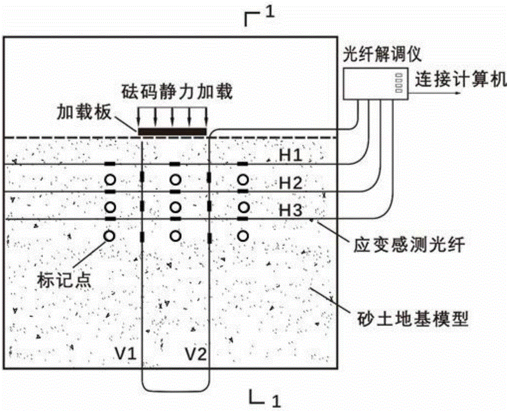
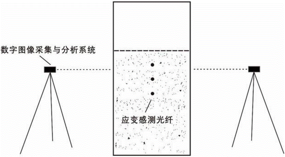
[0035] Such as figure 1 and figure 2 Shown, a soil deformation optical fiber monitoring calibration and test device, it includes calibration and test main box, strain sensing optical fiber, optical fiber demodulator, digital image acquisition and analysis device; the front and rear sides of the calibration and test main box It is a transparent rigid board, and the other two side boards are rigid boards, and the inside is filled with layered and compacted soil; the strain sensing optical fiber is laid horizontally and / or vertically in the soil segment by section; the optical fiber The demodulator is connected to the strain sensing optical fiber and collects strain data inside the soil; the digital image collection and analysis device is used to measure the displacement and strain of the soil in contact with the front and rear transparent rigid plates.

[0036] The two rigid side plates of the calibration and test main box have a number of small holes for passing through the o...


PUM


Abstract

The invention relates to a distributed optical fiber monitoring calibration and test device for soil deformation. The device comprises a calibration and test main box, stress sensing optical fibers, an optical fiber demodulation instrument and a digital image acquisition and analysis device; the front face and rear face of the test main box are transparent rigid plates, and the test main box is filled with soil which is compacted in a layered mode; the stress sensing optical fibers are laid in soil in the horizontal direction and/or vertical direction segment by segment; the optical fiber demodulation instrument is connected with the stress sensing optical fibers and acquires stress data in the soil; the digital image acquisition and analysis device is used for measuring displacement and stress of soil in contact with the front transparent rigid plate and the rear transparent rigid plate. By means of the distributed optical fiber monitoring calibration and test method and device, distributed optical fiber monitoring readings for soil deformation can be calibrated, the interaction and deformation coupling between the soil and the optical fibers are researched, and the spatial-temporal evolutional law of stress in the soil under different working conditions such as loading, unloading, digging and seepage is obtained.

Description

technical field [0001] The invention relates to the technical field of soil deformation and distributed optical fiber monitoring engineering, in particular to a soil deformation distributed optical fiber monitoring calibration and test device. Background technique [0002] The deformation of soil is an important index to evaluate the stable state of soil. For some large-scale projects such as slope filling, dam construction and tunnel excavation, the implementation of distributed deformation monitoring will help to obtain the abnormal parts of soil stress and deformation in time, and take corresponding engineering countermeasures to ensure the normal construction and operation of the project . Existing non-contact soil deformation measurement technologies, such as global positioning system, remote sensing, laser scanning, and photogrammetry, can only obtain deformation information on the soil surface, and their measurement accuracy is usually not high. Although rock and so...

Claims


Application Information

Patent Timeline
Patent Type & Authority Applications(China)
IPC IPC(8): G01B11/16
CPCG01B11/16
Inventor 朱鸿鹄张诚成施斌李飞许星宇董文文王德洋朱泳
Owner NANJING UNIV
Why Eureka
Try Eureka