Electromagnetic flowmeter and method of use thereof

A flowmeter and flow tube technology, applied in the field of electromagnetic flowmeters, can solve problems such as heavy wiring

Active Publication Date: 2020-01-21
SCHNEIDER ELECTRIC SYST USA INC
View PDF5 Cites 0 Cited by
  • Summary
  • Abstract
  • Description
  • Claims
  • Application Information

AI Technical Summary

Problems solved by technology

In addition, because separate sets of wires carry the signals for generating the electromagnetic field and the signals for detecting the induced voltage, the wiring between the transmitter and the other components of the magmeter can be cumbersome

Method used


Image

  • Electromagnetic flowmeter and method of use thereof
  • Electromagnetic flowmeter and method of use thereof
  • Electromagnetic flowmeter and method of use thereof

Examples


Embodiment Construction

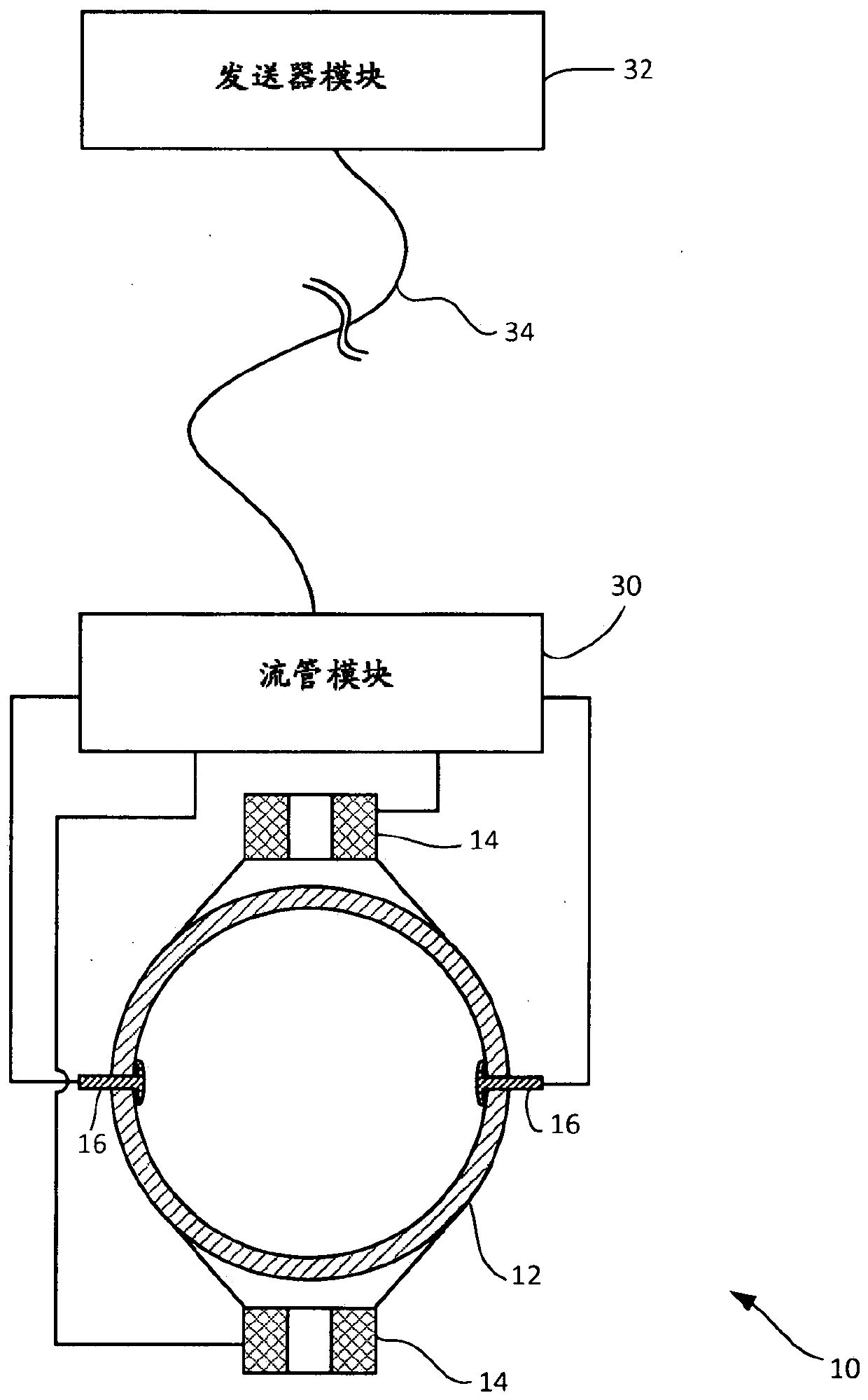
[0015] refer to figure 1 , an electromagnetic flowmeter for measuring the flow rate of a fluid is generally indicated by 10 . Electromagnetic flowmeter 10 includes a flow tube 12 configured to convey a flowing fluid. Flow tube 12 may be inserted into a pipe or other conduit or other suitable location in a processing facility. The illustrated flow meter 10 includes a pair of drive coils 14 (broadly a magnetic field source). The drive coil 14 is configured to deliver a reversible current for generating a magnetic field in fluid flowing through the flow tube 12 . The drive coil 14 in the illustrated embodiment is mounted in a diametrically opposite position relative to the flow tube 12 and is not in contact with the fluid. As discussed in more detail below, coil 14 receives a drive signal and generates a magnetic field in fluid flowing through flow tube 12 in response to the drive signal.

[0016] A pair of electrodes 16 (broadly voltage measuring instruments) configured to m...


PUM


Abstract

The present invention relates to electromagnetic flowmeters and methods of use thereof. A magnetic flow meter has a transmitter module that generates a drive signal for driving a magnetic field in a flowing fluid. The flow tube module samples the voltage induced in the fluid by the magnetic field and generates a measurement signal. A single signal path conveys the drive signal from the transmitter module to the flow tube module and the measurement signal from the flow tube module to the transmitter module. The flowtube module generates digital measurement signals. The flowtube module may include a processor for bundling the measurement signal with other information such as calibration data for the flowtube. In addition, the processor can control the timing of the operation of the flow pipe modules so that the flow pipe modules sample the induced voltage and send the measurement signals to the transmitter module at different times.

Description

technical field [0001] Aspects of the invention relate generally to electromagnetic flow meters. More particularly, aspects relate to an electromagnetic flowmeter having a flow tube module that sends a sampled measurement signal to a transmitter module that determines a flow rate from the sampled measurement signal. Background technique [0002] Electromagnetic flow meters are commonly used in a variety of industries to measure the flow rate of electrically conductive fluids flowing through pipes or other conduits. In principle, electromagnetic flowmeters generate a magnetic field in a conductive fluid. When a conductive fluid flows, the magnetic field induces a voltage difference between two locations in the fluid that are spaced apart in a direction transverse to the fluid flow. The size of the voltage difference is related to the flow rate. By detecting this voltage difference, the fluid flow rate can be measured. [0003] Conventionally, electromagnetic flowmeters ar...

Claims


Application Information

Patent Timeline
Patent Type & Authority Patents(China)
IPC IPC(8): G01F1/58
CPCG01F1/58G01F1/60G01F1/584
Inventor J·L·匹祖提A·德普鲁斯特
Owner SCHNEIDER ELECTRIC SYST USA INC
Why Eureka
Try Eureka