
Method for testing a circuit which is under test, and circuit configuration for carrying out the method

A circuit unit and circuit structure technology, applied in the direction of measuring electricity, measuring electrical variables, digital circuit testing, etc., can solve the problems of not allowing parallel testing, increasing the cost of the circuit unit to be tested and the overall cost of testing, etc., to save terminal units , reduce test cost, increase the effect of parallelism

Inactive Publication Date: 2005-02-09
INFINEON TECH AG
View PDF0 Cites 0 Cited by
  • Summary
  • Abstract
  • Description
  • Claims
  • Application Information

AI Technical Summary

Problems solved by technology

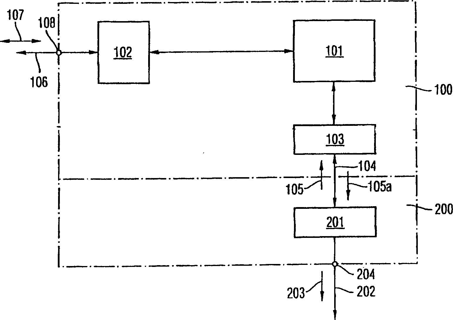
[0011] Therefore, the main disadvantage of the conventional circuit structure for testing the circuit unit under test is that, in addition to the addressing and control terminal unit 108 for enabling the memory cell array 101 in the circuit unit 100 under test, only Terminal unit 204 is provided for testing purposes
This extra connection pin untimely increases the cost of the circuit unit under test and the overall cost of testing
Furthermore, the conventional circuit architecture does not allow any significant degree of parallel testing

Method used


Image

  • Method for testing a circuit which is under test, and circuit configuration for carrying out the method
  • Method for testing a circuit which is under test, and circuit configuration for carrying out the method

Examples


Embodiment Construction

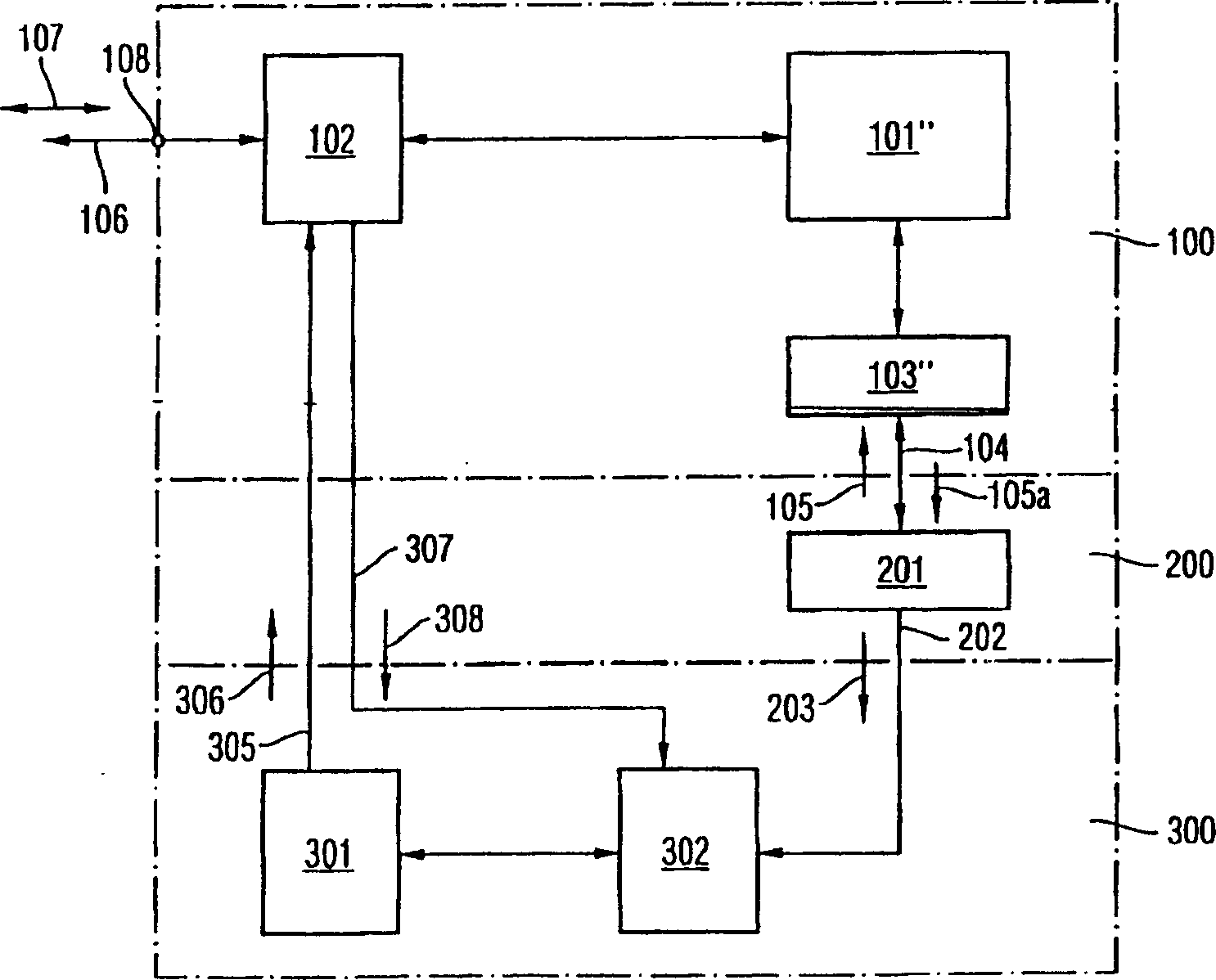
[0041] figure 1 The circuit structure shown includes three basic modules, namely, a circuit unit under test 100 , a testing device 200 and a combinational logic device 300 . It should be noted that the circuit unit 100 under test, the testing device 200 and the combinational logic device 300 in the following exemplary embodiments are arranged on a single circuit chip to form a single circuit unit.

[0042] That is to say, the circuit unit 100 under test is extended by the test device 200 and the combinational logic device 300, and only one addressing and control terminal unit 108 is required as an external connection.

[0043] It should be noted that although it is shown that the circuit unit under test 100, the testing device 200 and the combinational logic device 300 are arranged on a single chip, the circuit unit under test 100, the testing device 200 and the combinational logic device 300 may also be designed It is a discrete circuit unit.

[0044] The circuit unit 100 ...


PUM


Abstract

A circuit configuration for testing a circuit that is under test using a test device for providing a test mode, where test procedures are performed sequentially. The test procedures involve actual data that are output by the circuit under test on the basis of supplied test data are compared with prescribed nominal data in the test device. A combinational logic device for logically combining the sequentially output test results is provided such that result data indicate fault free operation of the circuit under test only if the actual data which are output match the prescribed nominal data in all of the sequentially performed test procedures. The result data is output via an addressing and control unit in the circuit under test.

Description

technical field [0001] The present invention generally relates to a method for testing a circuit unit, in particular to a method for testing a circuit unit under test having at least one memory cell array and at least one addressing and control unit, and a method utilizing The terminal unit provided on the circuit structure realizes the circuit structure of the method. Background technique [0002] There is an increasing need to implement a wide range of testing processes in parallel at low testing costs. The circuit unit to be tested is primarily a memory chip with increased complexity. In this case, the test cost is mainly determined by the test time and obtained according to the number of circuit units under test that can be tested within a predetermined time. [0003] The number of testable circuit units per unit time is also called throughput rate. In order to reduce the cost of each circuit unit under test as a whole, it has been proposed to reduce the test time or ...

Claims


Application Information

Patent Timeline
Patent Type & Authority Applications(China)
IPC IPC(8): G01R31/319G11C29/48
CPCG11C29/48G01R31/31908G11C29/1201
Inventor 欧文·塔尔曼
Owner INFINEON TECH AG
Learn More