Delamination propagation behavior simulation method of composite material multidirectional laminated plate on basis of cohesion model

A technology of composite materials and simulation methods, which is applied in the field of research and prediction of the delamination expansion behavior of composite multi-directional laminated boards. problems, to achieve the effect of reducing test costs and shortening the development cycle

Inactive Publication Date: 2014-02-26
BEIHANG UNIV
3 Cites 45 Cited by

AI-Extracted Technical Summary

Problems solved by technology

However, at present, most of the work on the interlayer properties of composite materials is still focused on the study of composite unidirectional laminates, and little is involved in the delamination expansion law of composite multi-directional laminate interfaces.
Due to the complex failu...

Abstract

The invention relates to a delamination propagation behavior simulation method of a composite material multidirectional laminated plate on the basis of a cohesion model. The method includes the following steps that (1) a geometric model is built according to structural parameters of a composite material multidirectional laminated plate test piece, (2) key parameters capable of reflecting interfacial behaviors are calculated, and material attributes are respectively set, (3) meshing is carried out on the geometric model of the composite material multidirectional laminated plate test piece, a module is assembled, and a three-dimensional finite element model is built, (4) a load and boundary conditions of the finite element model are determined according to practical situations and the load state of a composite material structure, (5) the finite element model based on the cohesion model is calculated and analyzed, a load displacement curve of a loading point is extracted, delamination propagation behaviors of the composite material multidirectional laminated plate are simulated to obtain the largest load value of the load displacement curve, and damage behaviors of the multidirectional laminated plate are predicted.

Application Domain

Technology Topic

Image

  • Delamination propagation behavior simulation method of composite material multidirectional laminated plate on basis of cohesion model
  • Delamination propagation behavior simulation method of composite material multidirectional laminated plate on basis of cohesion model
  • Delamination propagation behavior simulation method of composite material multidirectional laminated plate on basis of cohesion model

Examples

  • Experimental program(1)

Example Embodiment

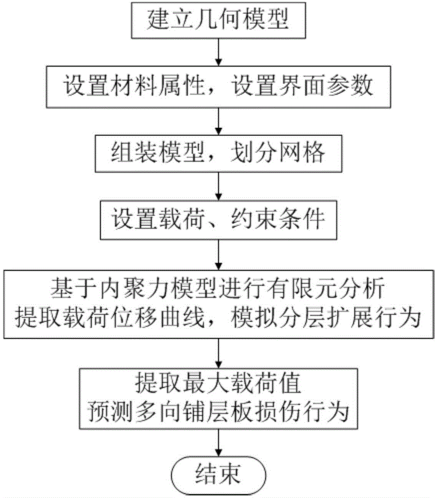
[0038] like figure 1 Shown, the inventive method is specifically realized as:
[0039] 1. According to the structural parameter values ​​of composite multi-directional laminated board specimens, the geometric model of the specimen is established in Abaqus software.
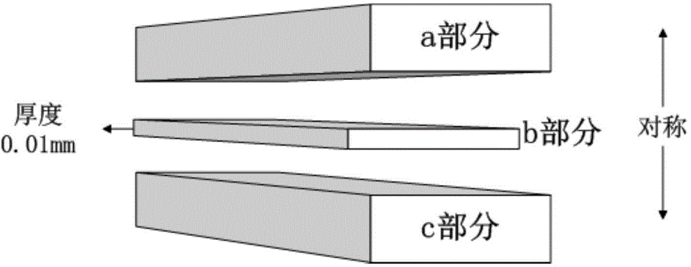
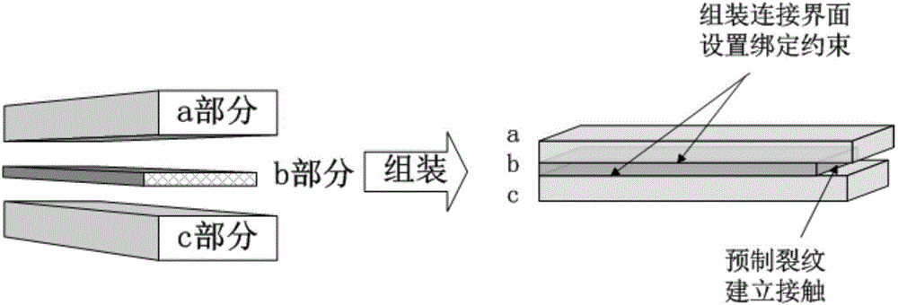
[0040] Open the Abaqus software, use the three-dimensional solid modeling function, draw the corresponding geometric contour diagram of the specimen in the two-dimensional plane according to the structural parameter values ​​of the multi-directional composite laminated plate specimen, and establish the three-dimensional geometry respectively by means of solid stretching model, such as figure 2 As shown, the two parts a and c are stretched to half of the actual thickness value along the thickness direction, and part b is stretched 0.01mm along the thickness direction.
[0041] 2. Determine the key parameters that reflect the interface behavior, and set the layup angle and material properties.
[0042] Define the local material direction, divide the geometric model of a and c according to the thickness of each layer, create a composite material layer and define the layer angle. When defining the layer angle, it is necessary to establish a corresponding local coordinate system according to the actual situation. According to the material properties Parameters, define the material properties of the geometric models a and c, select the linear constitutive relationship of the cohesive force model, introduce the critical strain energy release rate that changes with the crack length obtained from the test, and calculate the initial interface stiffness, interface strength, viscosity coefficient, etc. to reflect the interface behavior parameters, defining the b-model as the material properties corresponding to the cohesive regions.
[0043] 3. Mesh the geometric model separately, assemble the model, and establish a three-dimensional finite element model.
[0044] For parts a and c, distribute seeds evenly along the three directions of length, width and height, and divide the grid. The grid does not need to be very fine. Calculate the length of the cohesive area and determine the size and quantity of the cohesive force unit. According to the cohesive force unit size and unit number, evenly distribute seeds on part b, divide finer grids, assemble the geometric models in order from a, b, c, and set binding constraints on the assembly connection interface of geometric models a/b and b/c, Contact is established at prefabricated cracks, such as image 3 As shown, a three-dimensional finite element model is established.
[0045] 4. Determine the geometric model load and boundary conditions.
[0046] Determine the type I or I/II mixed load state, carry out force analysis on the composite material multi-directional laminated plate specimen, determine the constraints and load conditions of the specimen, and set the above constraints as boundary conditions on the load On the finite element model of the test piece, the load obtained from the force analysis is applied to the finite element model of the specimen.
[0047] 5. Simulate the layered expansion behavior of composite multi-directional laminated boards.
[0048] Perform stress analysis on the finite element model, calculate the strain energy release rate at the corresponding position, and obtain the crack length, then determine the critical energy release rate at the position according to the critical strain energy release rate-crack length relationship curve, and compare the current value with the critical value Compare and judge the failure of cohesive force unit and the expansion of cracks. The specific process is as follows: Figure 4 As shown, the finite element calculation results are obtained, and the load-displacement curve of the loading point is extracted by using the post-processing function of the finite element software, and the layered expansion behavior of the multi-directional composite laminate based on the cohesion model is simulated to obtain the maximum load value of the load-displacement curve , it is judged that when the actual load reaches the maximum value, the crack growth does not need to continue to increase the load, so as to realize the prediction of the damage behavior of the multi-directional laminated board.
[0049] Parts not described in detail in the present invention belong to the known techniques of those skilled in the art.

PUM

no PUM

Description & Claims & Application Information

We can also present the details of the Description, Claims and Application information to help users get a comprehensive understanding of the technical details of the patent, such as background art, summary of invention, brief description of drawings, description of embodiments, and other original content. On the other hand, users can also determine the specific scope of protection of the technology through the list of claims; as well as understand the changes in the life cycle of the technology with the presentation of the patent timeline. Login to view more.

Similar technology patents

Classification and recommendation of technical efficacy words

  • Shorten the development cycle
  • Reduce test costs

Embedded system firmware on-line upgrading system

ActiveCN101477471AReduce the difficulty of writingShorten the development cycleProgram loading/initiatingUpgradeFile system
Owner:HANGZHOU HIKVISION DIGITAL TECH

People also interested in

Why Eureka
Try Eureka