Separator for a water-steum separating device

A technology for separators and separation chambers, applied in the field of separators, which can solve problems such as long start-up time, slow load change speed, temperature change speed limit, etc.

Inactive Publication Date: 2004-12-01
SIEMENS AG
View PDF3 Cites 0 Cited by
  • Summary
  • Abstract
  • Description
  • Claims
  • Application Information

AI Technical Summary

Problems solved by technology

As a result, the permissible rate of temperature change is greatly restricted during start-up and load changes
This in turn can lead to undesirably longer cranking times, and consequently greater cranking losses, resulting in slower load changes
These inevitably limit the particularly high flexibility of the through-flow steam generator, at least when operating at high steam pressures

Method used


Image

  • Separator for a water-steum separating device
  • Separator for a water-steum separating device
  • Separator for a water-steum separating device

Examples


Embodiment Construction

[0019] specific implementation

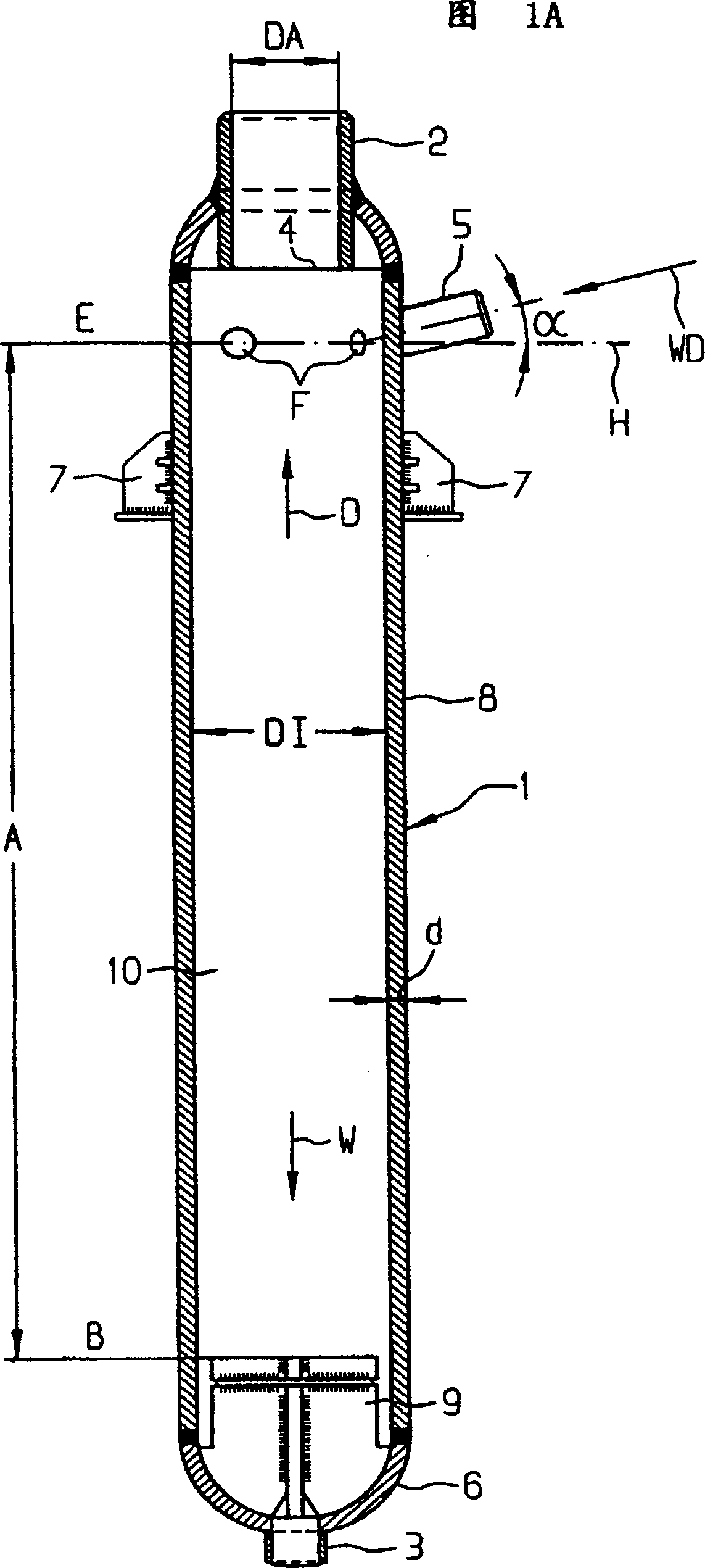
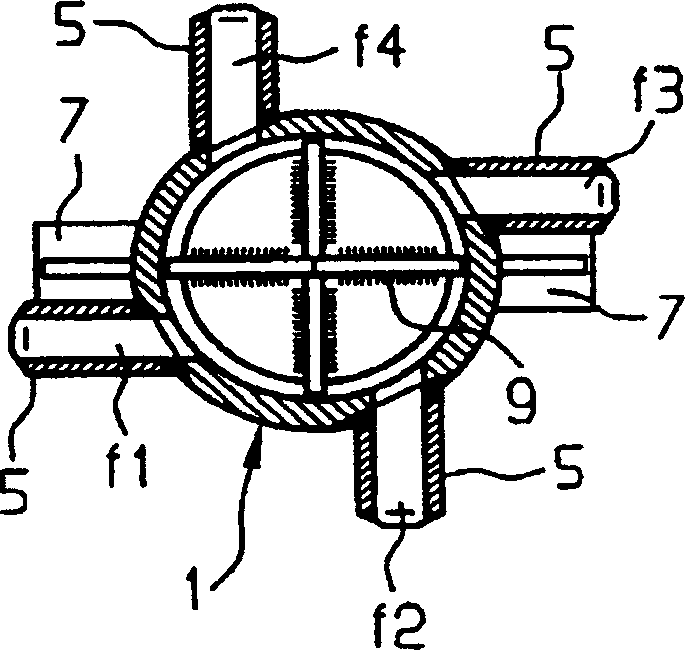
[0020] Figure 1a shows a separator or cyclone 1 in longitudinal section, while Figure 1b shows the separator in cross section. The separator 1 has an upper steam outlet 2 and a lower water outlet 3 . Below the steam discharge pipe 2, in the inflow or input plane E near its inflow port 4, some inlet pipes 5 are distributed along the periphery of the separator 1 for input of water to be divided into water W and steam D- Vapor mixture WD. Here, the inlet pipes 5 are on the one hand inclined at an angle α with respect to the horizontal plane H and on the other hand are connected tangentially to the separator. Below the inlet plane E of the inlet pipe 5 , on the wall 8 of the separator 1 there is a support clip 7 which holds the separator in an upright position.

[0021] Through the setting of the inlet pipe 5, the water-steam mixture WD flowing into the separator 1 flows downward to the bottom 6 of the separator 1 on the one hand, and forms a sw...


PUM


Abstract

The invention relates to a separator(1)for separating water(W)and steam(D). Said separator comprises an output conduit(2), an output conduit(3)and a separation chamber(10)between a number of input conduits(5)and a turbulence cancelling unit(7)which is placed upstream of said input conduit(3)on the water side. In order to minimise pressure losses while ensuring high medium throughput and effective separation, said separation chamber(10)has a length(A)which is at least 5 times bigger than its inner diameter(DI)and the ratio(K)of total flow section(F,[m<2>])of the input conduits(5)to the square of the inner diameter(DI,[m])of said separation chamber is comprised between 0.2 and 0.3. In a steam/water separating device(11), said separator(1)is connected to a water collector(15)in such a way that the upper end(OK)of said collector is located below the half-length(L)of the separator(1)determined from the lower end of said separator on the water side(UE).

Description

technical field [0001] The invention relates to a separator for separating water and steam, the water side and the steam side of which have a discharge pipe respectively. The separator has a separating chamber which is located between inlet lines and a vortex breaker upstream of the outlet line on the water side. The invention also relates to a water-steam separation device, especially for a through-flow steam generator. The separating device has at least one separator of the above-mentioned type, which is connected to a water collecting container. Background technique [0002] A centrifugal water separator is known from patent document DAS 1 081 474, the ratio of diameter to height of which is approximately 1:6 or more. Also by Juergen Vollrath published in "Technische Ueberwachung" (Technische Ueberwachung) magazine No. 9 (1968), No. 2, the paper "Separation of steam in boiling water- and boiling superheated reactors", The ratio of the diameter of the vapor-side outlet ...

Claims


Application Information

Patent Timeline
Patent Type & Authority Patents(China)
IPC IPC(8): B01D45/12F22B37/32
CPCF22B37/32F22B37/26
Inventor 霍尔格·施米特埃伯哈德·威特乔
Owner SIEMENS AG
Why Eureka
Try Eureka