Steam compressor

一种压缩机、气缸的技术,应用在压力泵、机械设备、机器/发动机等方向,能够解决不再能保证操作流体安全操作、操作流体准确液位测量不再可能等问题,达到可靠操作、低结构支出、长使用寿命的效果

Inactive Publication Date: 2011-07-20
LINDE AG
View PDF2 Cites 0 Cited by
  • Summary
  • Abstract
  • Description
  • Claims
  • Application Information

AI Technical Summary

Problems solved by technology

However, in such conventional compressors, due to the short cycle times in the compressor cylinders, accurate level measurement of the operating fluid is no longer possible, whereby safe operation of a specific sufficient amount of operating fluid in the moving cylinders can no longer be guaranteed

Method used


Image

  • Steam compressor
  • Steam compressor

Examples


Embodiment Construction

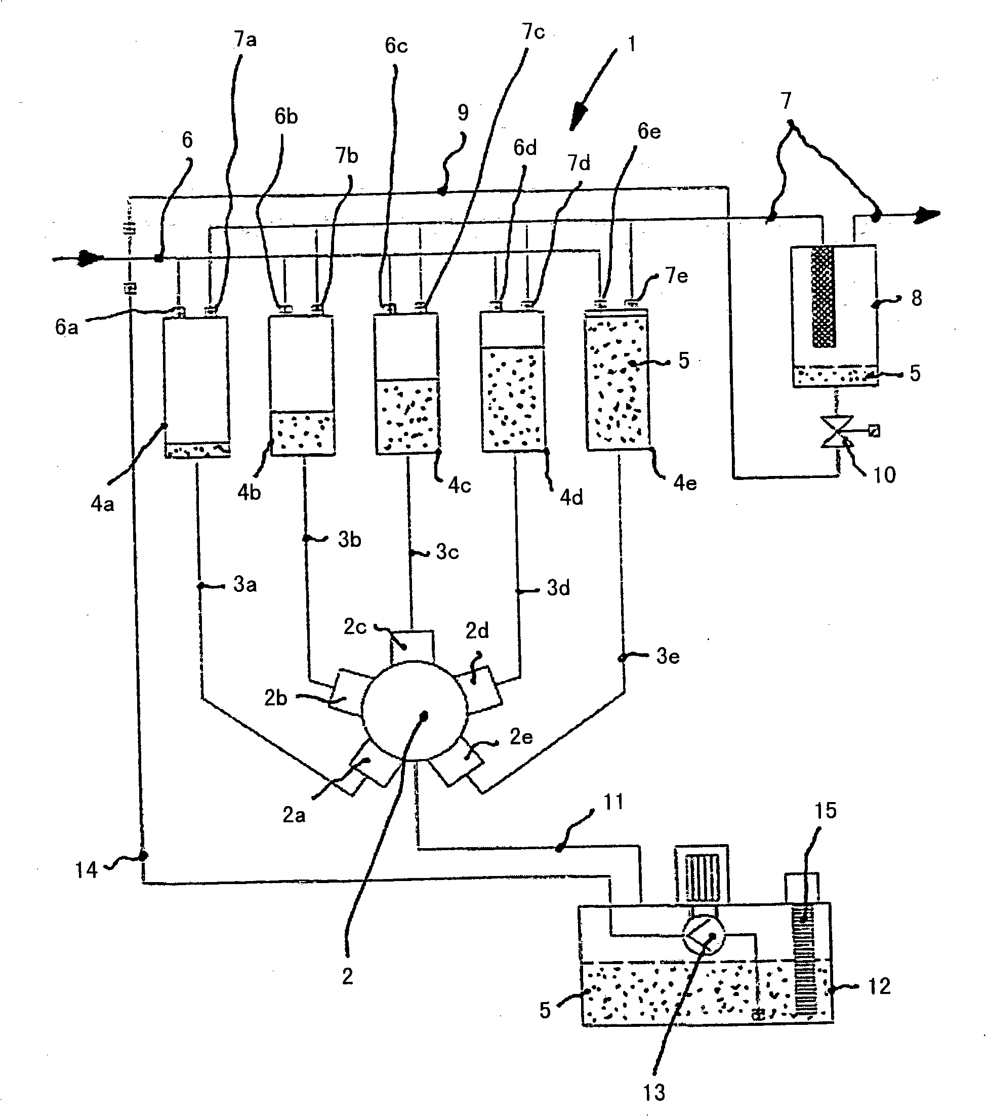
[0017] In the figure, a circuit diagram shows a compressor 1 according to the invention. The compressor 1 has a mobile machine configured as a piston machine 2, for example a radial piston machine, provided with several cylinder chambers 2a, 2b, 2c, 2d, 2e. Each cylinder chamber 2a, 2b, 2c, 2d, 2e (in which a piston not shown is respectively movably mounted) is connected to a compressor cylinder 4a, 4b, 4c by means of a connecting duct 3a, 3b, 3c, 3d, 3e , 4d, 4e are connected. In the compressor cylinders 4 a , 4 b , 4 c , 4 d , 4 e is located an operating fluid 5 in the form of an ionic fluid which is movable by means of the piston machine 2 .

[0018] The compressor cylinders 4a, 4b, 4c, 4d, 4e are connected on the input side via inlet valves 6a, 6b, 6c, 6d, 6e respectively to inlet lines 6 for the medium to be compressed, eg natural gas or hydrogen. In order to increase the input pressure and thus the output performance, a pre-compressor can be associated with the inlet d...


PUM


Abstract

The invention relates to a compressor (1) for compressing gaseous media having at least one compressor cylinder (4a; 4b; 4c; 4d; 4e) that is connected to an inlet line (6) and an outlet line (7) for tThe invention relates to a compressor (1) for compressing gaseous media having at least one compressor cylinder (4a; 4b; 4c; 4d; 4e) that is connected to an inlet line (6) and an outlet line (7) for the medium, wherein an operating fluid (5), particularly an ionic operating fluid, is disposed in the compressor cylinder (4a; 4b; 4c; 4d; 4e), which is cooperating with a displacement machine (2), whehe medium, wherein an operating fluid (5), particularly an ionic operating fluid, is disposed in the compressor cylinder (4a; 4b; 4c; 4d; 4e), which is cooperating with a displacement machine (2), wherein the displacement machine (2) is configured as a piston machine having at least one cylinder space (2a; 2b; 2c; 2d; 2e), and each cylinder space (2a; 2b; 2c; 2d; 2e) cooperates with a compressor crein the displacement machine (2) is configured as a piston machine having at least one cylinder space (2a; 2b; 2c; 2d; 2e), and each cylinder space (2a; 2b; 2c; 2d; 2e) cooperates with a compressor cylinder (4a; 4b; 4c; 4d; 4e). In order to solve the task of providing a compressor, which ensures safe operation at minimal construction effort, the invention proposes that a separating device (8) forylinder (4a; 4b; 4c; 4d; 4e). In order to solve the task of providing a compressor, which ensures safe operation at minimal construction effort, the invention proposes that a separating device (8) forthe operating fluid (5) is associated with the outlet line (7) of the compressor (1), wherein the separating device (8) cooperates with the inlet line (6) of the compressor (1) for the recirculation the operating fluid (5) is associated with the outlet line (7) of the compressor (1), wherein the separating device (8) cooperates with the inlet line (6) of the compressor (1) for the recirculationof the operating fluid (5).of the operating fluid (5).

Description

technical field [0001] The invention relates to a compressor for compressing a gaseous medium with at least one compressor cylinder connected to inlet and outlet ducts of the medium, with an operating fluid, in particular an ionic operating fluid, arranged in the compressor cylinder, so Said fluid is connected to a moving machine, wherein the moving machine is configured as a piston machine having at least one cylinder chamber and each cylinder chamber is connected to a compressor cylinder. Background technique [0002] Such compressors are used for the compression of gaseous media such as natural gas or hydrogen. The medium is moved here by means of the operating fluid in the compressor cylinder, whereby such a compressor is designed as a vapor compressor. Ionic fluids can be used as fluids. However, it is equally possible to use fluids with lower vapor pressure or fluids with lower gas solubility. Such fluids have in common that they do not dissolve in the medium and ca...

Claims


Application Information

Patent Timeline
Patent Type & Authority Patents(China)
IPC IPC(8): F04F1/06F04F1/10
CPCF04F1/10F04F1/06
Inventor R·阿德勒H·迈尔
Owner LINDE AG
Why Eureka
Try Eureka