USB Type-C interface circuit and control device thereof

An interface circuit and interface controller technology, applied in the USB field, can solve the problem of high power consumption

Active Publication Date: 2016-08-17
HYNETEK SEMICON CO LTD
View PDF4 Cites 45 Cited by
  • Summary
  • Abstract
  • Description
  • Claims
  • Application Information

AI Technical Summary

Problems solved by technology

[0005] In order to overcome the above-mentioned technical problems, the purpose of the present invention is to provide a USB Type-C interface circui...

Method used


Image

  • USB Type-C interface circuit and control device thereof
  • USB Type-C interface circuit and control device thereof
  • USB Type-C interface circuit and control device thereof

Examples


Embodiment 1

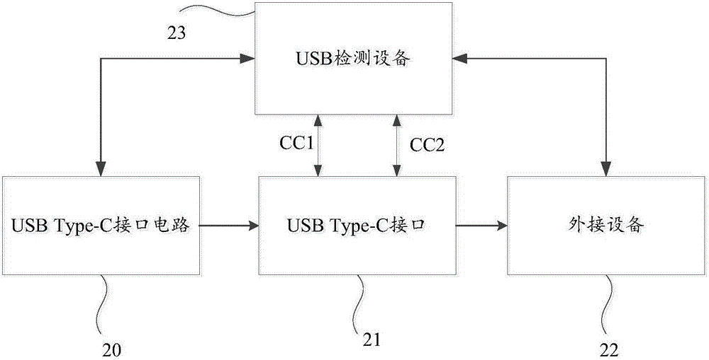
[0078] Please refer to figure 2 , figure 2 It is a functional block diagram of a USB Type-C interface circuit provided by Embodiment 1 of the present invention. Such as figure 2 As shown, the USB Type-C interface circuit 20 is connected to an external device 22 through a USB Type-C interface 21 , and detects the external device 23 by controlling a USB detection device 23 . Specifically, the USB detection device 23 is respectively connected to the first detection pin CC1 and the second detection pin CC2 of the USB Type-C interface 21, and identifies the external device through the first detection pin CC1 and the second detection pin CC2 23 type or direction of insertion. The external device 23 here includes a charger with a USB Type-C interface, a smart phone, a smart stereo, a smart TV, a desktop computer, a tablet computer, a smart bracelet, a smart watch, and the like.

[0079] Please also refer to figure 2 with Figure 2a , Figure 2a It is a functional block dia...

Embodiment 2

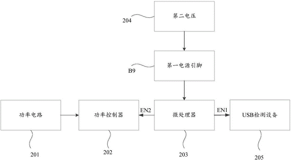
[0107] Please refer to Image 6 , Image 6 It is a schematic structural diagram of a USB Type-C interface circuit provided by Embodiment 2 of the present invention. Such as Image 6 As shown, the USB Type-C interface circuit includes:

[0108] a power circuit 61, configured to output a first voltage;

[0109] a power controller 62, configured to be connected to the power circuit, and output a control signal to control the power circuit to output the first voltage;

[0110] The microprocessor 63 is used to connect the first power supply pin B9, the second power supply pin A9 and the power controller 62 of the USB Type-C interface respectively, and when the USB Type-C interface is not connected to an external device, Receiving the second voltage input from the first power supply pin B9 or the second power supply pin A9 of the USB Type-C interface, outputting a low level signal through the first enable terminal to make the USB detection device 64 in a standby state, through ...

Embodiment 3

[0117] Please refer to Figure 7 , Figure 7 It is a schematic structural diagram of a USB Type-C interface circuit provided by Embodiment 3 of the present invention. Such as Figure 7 As shown, the USB Type-C interface circuit includes:

[0118] a power circuit 71, configured to output the first voltage;

[0119] a power controller 72, configured to be connected to the power circuit, and output a control signal to control the power circuit to output the first voltage;

[0120] The microprocessor 73 is used to connect the first power supply pin, the second power supply pin, the third power supply pin and the power controller of the USB Type-C interface respectively, and when the USB Type-C interface is not connected to an external device, receive the second voltage input from the first power supply pin or the second power supply pin or the third power supply pin of the USB Type-C interface, and output a low level signal through the first enable terminal to enable the USB t...


PUM


Abstract

The invention discloses a USB Type-C interface circuit and a control device thereof. The circuit comprises a power circuit, a power controller and a microprocessor; the power circuit is used for outputting the first voltage; the power controller is used for being connected with the power circuit and outputting a control signal to control the power circuit to output the first voltage; the microprocessor is used for being connected with a first power supply pin of a USB Type-C interface and the power controller separately, receiving the second voltage input by the first power supply pin of the USB Type-C interface when the USB Type-C interface is not connected with equipment, outputting a low level signal through a first enabling end to enable USB detection equipment to be in a standby state and outputting a low level signal through a second enabling end to enable the power controller to be in a standby state. Accordingly, by switching off the USB detection equipment and the power controller on the standby condition, the USB detection equipment and the power controller do not need to continuously work in 24 hours, and therefore the standby power consumption of the complete circuit is reduced.

Description

technical field [0001] The invention relates to the technical field of USB, in particular to a USB Type-C interface circuit and a control device thereof. Background technique [0002] The USB specification organization announced a new type of USB interface, the USB Type-C interface. Compared with the old-fashioned USB Type-A and USB Type-B interfaces, this new type of USB Type-C interface has the following characteristics: 1. The interface size is thinner and smaller; 2. The data transmission speed is faster; 3. The transmission power capability is stronger; 4. Support positive and negative insertion. [0003] Please refer to figure 1 , figure 1 It is a schematic diagram of the interface definition of the USB Type-C socket. Such as figure 1 As shown, the interface is divided into two rows, and each row has 12 signal pins. Among them, 4 power supply pins are the power supply VBUS of USB, which are A4, B4, A9 and B9. In addition, there are 4 ground pins that are the gro...

Claims


Application Information

Patent Timeline
IPC IPC(8): G06F1/32G06F13/38
CPCG06F1/3253G06F13/385Y02D10/00
Inventor 刘靖
Owner HYNETEK SEMICON CO LTD
Why Eureka
Try Eureka