Method and device for calculating depositional stage micro-amplitude palaeohigh
A technique of amplitude and quasi-structural amplitude, applied in the field of geological exploration, can solve problems such as poor calculation accuracy
Active Publication Date: 2016-08-17
CHINA UNIV OF PETROLEUM (BEIJING) +1
View PDF4 Cites 9 Cited by
- Summary
- Abstract
- Description
- Claims
- Application Information
AI Technical Summary
Problems solved by technology
[0005] Embodiments of the present invention provide a method and device for calculating a paleo-uplift with a slight amplitude during the deposition period, so as to solve the problem that the prior art can only calculate the paleo-uplift wi
Method used
View moreImage
Smart ImageViewing Examples
Examples
 PUM
 Abstract
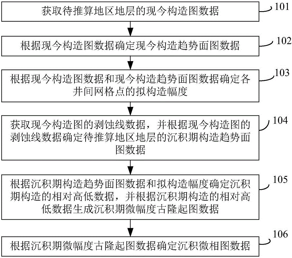
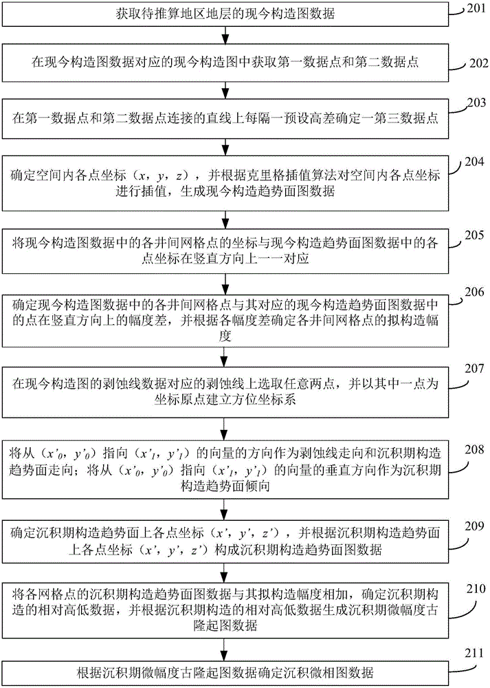
The invention provides a method and device for calculating depositional stage micro-amplitude palaeohigh and relates to the technical field of geological exploration. The method comprises the steps of determining current structural trend-surface map data according to current structural map data, and determining a to-be-constructed amplitude of each inter-well grid point, wherein the to-be-constructed amplitude is vertical direction amplitude of a point on a current structural map relative to the current structural trend-surface; determining depositional stage structural trend-surface map data of a to-be-calculated regional stratum according to a ni-out line of the current structural map; determining relatively high and low data of the depositional stage structure according to the depositional stage structural trend-surface map data and the to-be-constructed amplitude, generating depositional stage micro-amplitude palaeohigh map data according to the relatively high and low data of the depositional stage structure, and determining map data of sedimentary microfacies. According to the method and device for calculating the depositional stage micro-amplitude palaeohigh, the problems that in the prior art, only palaeohigh with the uplift amplitude of about 50 m and above can be calculated and the precision of calculating depositional stage micro-amplitude palaeohigh with the uplift amplitude of only 20 m and even below is poor can be solved.
Description
technical field [0001] The invention relates to the technical field of geological exploration, in particular to a calculation method and device for a slight-amplitude paleo-uplift in the sedimentary period. Background technique [0002] Currently, in the world, oil and gas reserves directly related to paleogeomorphology are greater than 5×10 8 There are many large oil and gas fields with bbl oil equivalent. Paleogeomorphology refers to certain types of landforms formed by factors such as structural deformation, sedimentary filling, differential compaction, and weathering denudation in the geological history period, which remain until today or are buried underground. The oil and gas traps related to paleogeomorphology are divided into two categories: one is oil and gas traps related to sedimentary paleogeomorphology, such as: reefs, grain beaches, sand bars, sand dunes, erosion valleys, etc.; the other is related to denudation Oil and gas traps related to paleogeomorphology...
Claims
Login to View More Application Information
Patent Timeline
 IPC IPC(8): G06F17/50G06Q50/02
CPCG06F30/13G06Q50/02
Inventor 王建国常宏杜支文顾岱鸿孙振成育红王彦良纪彦博杨璐菁
Owner CHINA UNIV OF PETROLEUM (BEIJING)
Features
- R&D
- Intellectual Property
- Life Sciences
- Materials
- Tech Scout
- Unparalleled Data Quality
- Higher Quality Content
- 60% Fewer Hallucinations
Learn More Browse by: Latest US Patents, China's latest patents, Technical Efficacy Thesaurus, Application Domain, Technology Topic, Popular Technical Reports.
© 2025 PatSnap. All rights reserved.Legal|Privacy policy|Modern Slavery Act Transparency Statement|Sitemap|About US| Contact US: help@patsnap.com


