Supercharge Your Innovation With Domain-Expert AI Agents!

Implementation method for reducing short circuit protection time of electromagnetic release

An electromagnetic release and short-circuit protection technology, which is applied in the direction of protection switch operation/release mechanism, etc., can solve problems such as poor protection circuit, power distribution circuit loss of voltage, and influence on the normal operation of other equipment, and achieve short-circuit instantaneous protection The effect of shortening the time

Inactive Publication Date: 2016-08-17
WUHAN HANGJIU ELECTRIC
View PDF5 Cites 2 Cited by
  • Summary
  • Abstract
  • Description
  • Claims
  • Application Information

AI Technical Summary

Problems solved by technology

When a short circuit occurs in the circuit, if the circuit breaker does not trip in time, that is, the short circuit cannot be cut off before the phase is lost, it will cause voltage loss in other bus distribution circuits and affect the normal operation of other equipment
The release is the core component of the circuit breaker. At present, the iron core inside the traditional electromagnetic release of the circuit breaker is usually made of low-carbon steel material, and the magnetic permeability is small, which causes the short-circuit instantaneous tripping of the circuit breaker to be slow. In some special Can not protect the circuit well in the power distribution environment

Method used


Image

  • Implementation method for reducing short circuit protection time of electromagnetic release
  • Implementation method for reducing short circuit protection time of electromagnetic release
  • Implementation method for reducing short circuit protection time of electromagnetic release

Examples


Embodiment Construction

[0015] The present invention will be further described below in conjunction with the accompanying drawings.

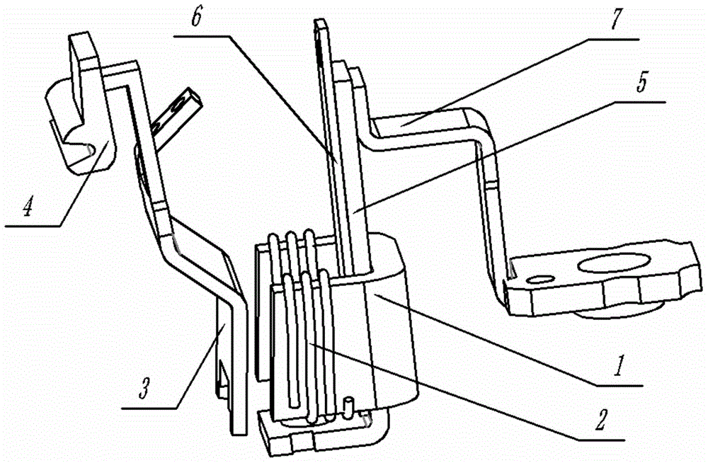
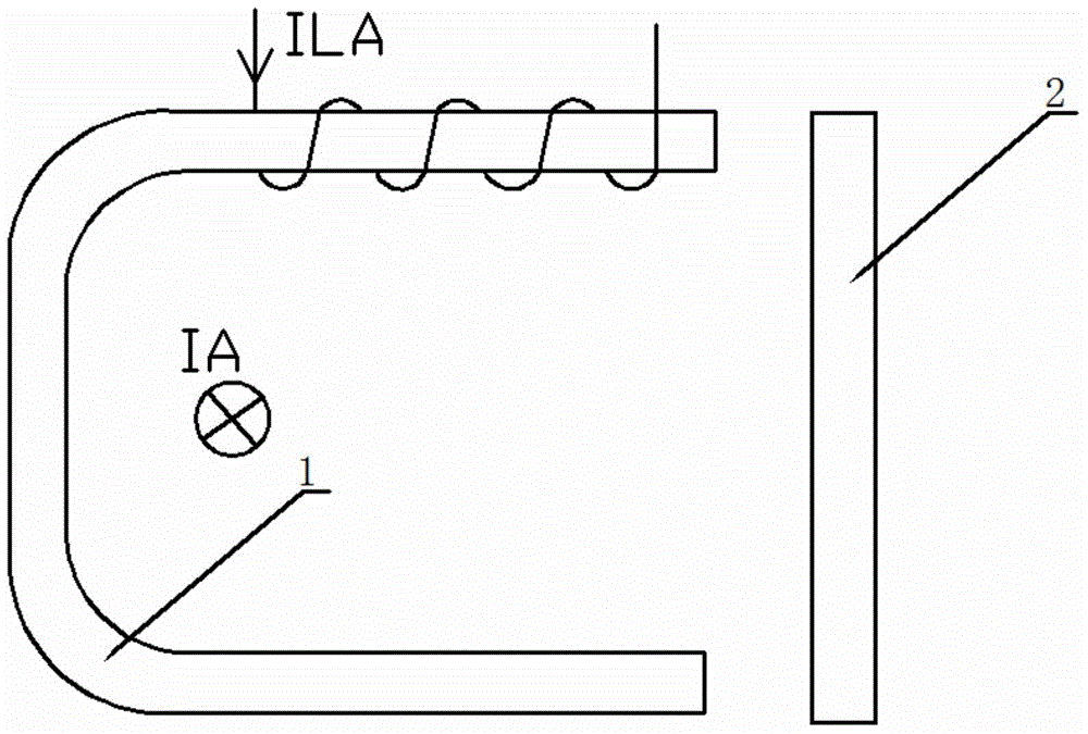
[0016] figure 1 It is a schematic diagram of the three-dimensional structure of the main part of the circuit breaker electromagnetic tripper short-circuit protection unit implemented in the present invention. The heating element 5 is welded on one end of the bracket 7, and is electrically connected to the main circuit. The bimetallic strip 6 is close to the heating element 5, U The iron core 1 is fixed on the heating element 5, the auxiliary release coil 2 is wound on both sides of the U-shaped iron core 1, the armature 3 and the tripping rod 4 are located on the opposite side of the U-shaped iron core 1, and the armature 3 drives Trip lever action.

[0017] Such as figure 1 As shown, the short-circuit instantaneous protection characteristic of the circuit breaker electromagnetic tripper implemented in the present invention is mainly completed by the U-shaped iron co...


PUM


Abstract

The invention relates to a method for shortening the short-circuit protection time of an electromagnetic tripper. The tripper protection unit includes a U-shaped iron core, an auxiliary tripping coil, an armature, a tripping rod, a heating element, a bimetallic sheet and an auxiliary tripping unit. Coil power supply circuit. It is characterized in that the traditional iron core is changed from low-carbon steel material to silicon steel sheet material, the magnetic field force generated by the U-shaped iron core is increased, the armature pulls in faster, and the short-circuit instantaneous protection time is shortened; the U-shaped iron core is equipped with auxiliary tripping The coil shortens the protection time when there is a lot of undervoltage in the short circuit state, offsets part of the magnetic field force when overloaded, and maintains the overload protection characteristics. When the circuit is short-circuited, the U-shaped iron core generates a huge magnetic field force to attract the armature, so that the trip lever operates to disconnect the circuit. The invention can effectively shorten the short-circuit instantaneous protection time of the electromagnetic tripper, and when a large-current short circuit occurs in the circuit, the tripping mechanism will act before the phase is missing, and the circuit can be cut off more reliably and quickly.

Description

technical field [0001] The invention relates to a realization method for shortening the short-circuit protection time of an electromagnetic tripper. Background technique [0002] The circuit breaker is a terminal protection device widely used in electrical terminal power distribution devices. The short-circuit instantaneous tripping capability of the circuit breaker is a key performance indicator, which can ensure that the circuit is quickly protected when a short circuit occurs in the circuit without affecting other equipment. When a short circuit occurs in the circuit, if the circuit breaker does not trip in time, that is, the short circuit cannot be cut off before the phase is lost, it will cause voltage loss in other bus distribution circuits and affect the normal operation of other equipment. The release is the core component of the circuit breaker. At present, the iron core inside the traditional electromagnetic release of the circuit breaker is usually made of low-car...

Claims


Application Information

Patent Timeline
Patent Type & Authority Applications(China)
IPC IPC(8): H01H71/24
Inventor 王映波雷元林盖忠伟魏彦张家贵熊天学吴小丽程林林
Owner WUHAN HANGJIU ELECTRIC
Features
  • R&D
  • Intellectual Property
  • Life Sciences
  • Materials
  • Tech Scout
  • Unparalleled Data Quality
  • Higher Quality Content
  • 60% Fewer Hallucinations
Learn More