Supercharge Your Innovation With Domain-Expert AI Agents!

Spaceflight vehicle ground redundant power supply system and method

A technology of power supply system and carrier, applied in the direction of power network operating system integration, information technology support system, electrical components, etc., can solve problems such as potential safety hazards, failure of control systems to work normally, damage to control system equipment, etc., and achieve reliable switching Effect

Inactive Publication Date: 2020-12-25
BEIJING LANDSPACETECH CO LTD
View PDF5 Cites 0 Cited by
  • Summary
  • Abstract
  • Description
  • Claims
  • Application Information

AI Technical Summary

Problems solved by technology

With the rapid development of aerospace technology, aerospace electronic equipment is increasing day by day, and power consumption is increasing. These changes make the design of power supply and distribution system more complicated, and at the same time put forward higher requirements for the reliability and safety of power supply.
Increased power consumption may make ground power supplies more prone to sporadic failures
Once the control system on the arrow is powered off due to the power supply equipment, the test process cannot continue, the product will stop working, and the product on the arrow will be damaged in severe cases.
Especially when the launch process of the space vehicle is in progress, the front end is unattended. If there is a failure due to an abnormal ground power supply, the operator needs to go to the scene to perform emergency investigations, maintenance and other operations, which poses a greater safety hazard
[0003] At present, the commonly used power supply and distribution system for measurement, control and control is a ground power supply that supplies power to the system on the arrow. In this state, any failure of the power supply will cause the control system to fail to work normally, and the reliability requirements for a single power supply equipment are greatly increased. increase, and the occurrence of faults will also cause damage to the control system equipment

Method used


Image

  • Spaceflight vehicle ground redundant power supply system and method
  • Spaceflight vehicle ground redundant power supply system and method
  • Spaceflight vehicle ground redundant power supply system and method

Examples


Embodiment Construction

[0023] The characteristics and exemplary embodiments of various aspects of the present invention will be described in detail below. In order to make the purpose, technical solutions and advantages of the present invention clearer, the present invention will be further described in detail below in conjunction with the accompanying drawings and specific embodiments. It should be understood that the specific embodiments described here are only configured to explain the present invention and to exemplify the principle of the present invention, and are not configured to limit the present invention. Additionally, the mechanical components in the figures are not necessarily drawn to scale. For example, the size of some structural components or regions in the drawings may be exaggerated for other structural components or regions, so as to facilitate the understanding of the embodiments of the present invention.

[0024] The orientation words appearing in the following description are ...


PUM


Abstract

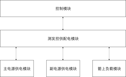
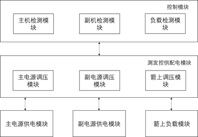
The invention provides a spaceflight vehicle ground redundant power supply system. The ground redundant power supply system comprises a main power supply module, an auxiliary power supply module, a test launch control power supply and distribution module, an on-rocket load module and a control module; the main power supply module and the auxiliary power supply module are connected to the test launch control power supply and distribution module in a hot standby redundancy control mode, and the voltage amplitude of the main power supply module is larger than that of the auxiliary power supply module; the control module automatically selects the main power supply module or the auxiliary power supply module to supply power to the on-rocket load module. The redundant power supply system ensuresthat the system test launch control operation is carried out smoothly, and realizes reliable switching of power supply of a ground power supply.

Description

technical field [0001] The invention relates to the field of redundant power supply, in particular to a ground redundant power supply system and method for an aerospace vehicle. Background technique [0002] In the test launch control system of space vehicle, the power supply and distribution system on the arrow is an important part of it. With the rapid development of aerospace technology, aerospace electronic equipment is increasing day by day, and power consumption is increasing. These changes make the design of power supply and distribution system more complicated, and at the same time, higher requirements are put forward for the reliability and safety of power supply. Increased power consumption can make ground power supplies more prone to sporadic failures. Once the control system on the arrow is powered off due to the power supply equipment, the test process will not continue, the product will stop working, and the product on the arrow will be damaged. Especially wh...

Claims


Application Information

Patent Timeline
Patent Type & Authority Applications(China)
IPC IPC(8): H02J3/00H02J9/04
CPCH02J9/04H02J3/0073Y02B70/30Y04S20/20
Inventor 郑然柴东平孙飞刘浩茫赵鹏飞潘晓明徐昕
Owner BEIJING LANDSPACETECH CO LTD
Features
  • R&D
  • Intellectual Property
  • Life Sciences
  • Materials
  • Tech Scout
  • Unparalleled Data Quality
  • Higher Quality Content
  • 60% Fewer Hallucinations
Learn More