Broadband microstrip antenna

A microstrip antenna and broadband technology, applied in the field of antennas, can solve the problems of narrow operating bandwidth and limited application range, and achieve the effect of high operating bandwidth

Inactive Publication Date: 2016-08-17
TOP VICTORY INVESTMENTS
View PDF5 Cites 2 Cited by
  • Summary
  • Abstract
  • Description
  • Claims
  • Application Information

AI Technical Summary

Benefits of technology

This patented technology improves how radiation from an antenna's main part changes its electrical properties by creating waves called spiraling patterns along certain parts or sides of it instead of just shaping them like circles around one another. These technical improvements make better performance for wireless communication devices with multiple frequency bands.

Problems solved by technology

This patented describes how conventional microwave technology works well for transmitting signals wirelessly due to their compact design that allows them to fit into smaller devices while still being able to transmit radio waves effectively without interference or distortion caused by other components within these devices. However, there are limitations associated with this type of device's performance at high frequencies where it cannot efficiently emit enough energy needed for effective communication.

Method used


Image

  • Broadband microstrip antenna
  • Broadband microstrip antenna
  • Broadband microstrip antenna

Examples


Embodiment Construction

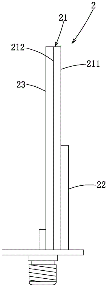
[0027] refer to figure 2 An embodiment of the broadband microstrip antenna 2 of the present invention includes an insulating substrate 21, a radiation piece 23, and a grounding piece 22, which are used to radiate the fed-in electrical signal to the outside after the electrical signal is fed in.

[0028] The base 21 is rectangular and has a first surface 211 and a second surface 212 opposite to the first surface 211 .

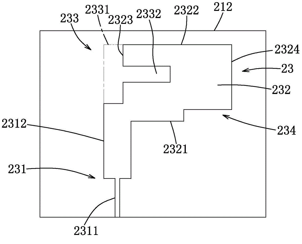
[0029] see also image 3 The radiation sheet 23 is made of conductive material and formed on the second surface 212, including a feeder extending from one side of the second surface 212 parallel to the other side and crossing the ground sheet 22 and inputting a power supply signal. Incoming arm 231, a rectangular radiating body 232 connected to the feeding arm 231, a notch 233 extending from a short side of the radiating body 232 parallel to its long side, and a radiating body 232 oppositely formed The other short side of the notch 233 is along the auxiliary ...


PUM


Abstract

A broadband microstrip antenna, comprising an insulating substrate, a grounding sheet and a radiation sheet, the insulating substrate has a first surface and a second surface opposite to the first surface, the grounding sheet is made of conductive material And formed on the first surface, the radiation plate is made of conductive material and formed on the second surface, and includes a feed-in extending inward from the edge of the second surface and crossing the ground plate and supplying signal input arm, a radiation body extending from the feeding arm away from the ground plate, and a notch extending from a side of the radiation body toward a first direction, and the notch makes the side of the radiation body present a meandering shape In turn, the current distribution on the surface of the radiating body is changed, resulting in a high operating bandwidth.

Description


Claims


Application Information

Patent Timeline
Owner TOP VICTORY INVESTMENTS
Why Eureka
Try Eureka