Electric-power connection hardware fitting for overhead line
A technology for connecting fittings and overhead lines. It is applied in the direction of conductive connection, electrical component connection, needle point/slotted plate contact piece used for penetrating insulated wire/cable core wire, etc. It can solve problems such as easy loosening and poor firmness. To achieve the effect of ensuring stability, reliability and excellent anti-loosening effect
- Summary
- Abstract
- Description
- Claims
- Application Information
AI Technical Summary
Problems solved by technology
Method used
Image

Examples
Embodiment 1)
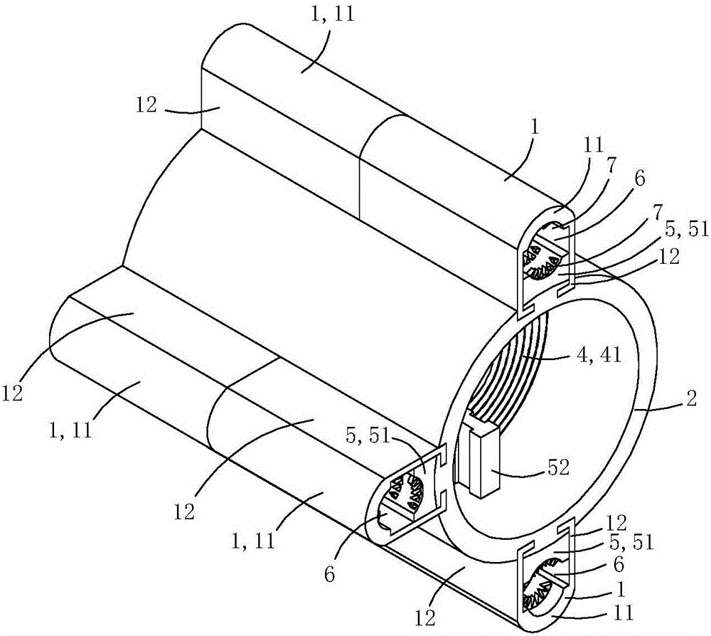
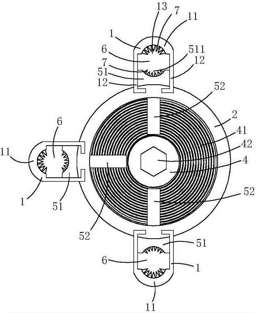
[0016] This embodiment is a power connection fitting for overhead lines, see Figure 1 to Figure 4 As shown, it includes a core tube 2, two sets of crimping components 3, two flat nuts 4 and two sets of crimping components.
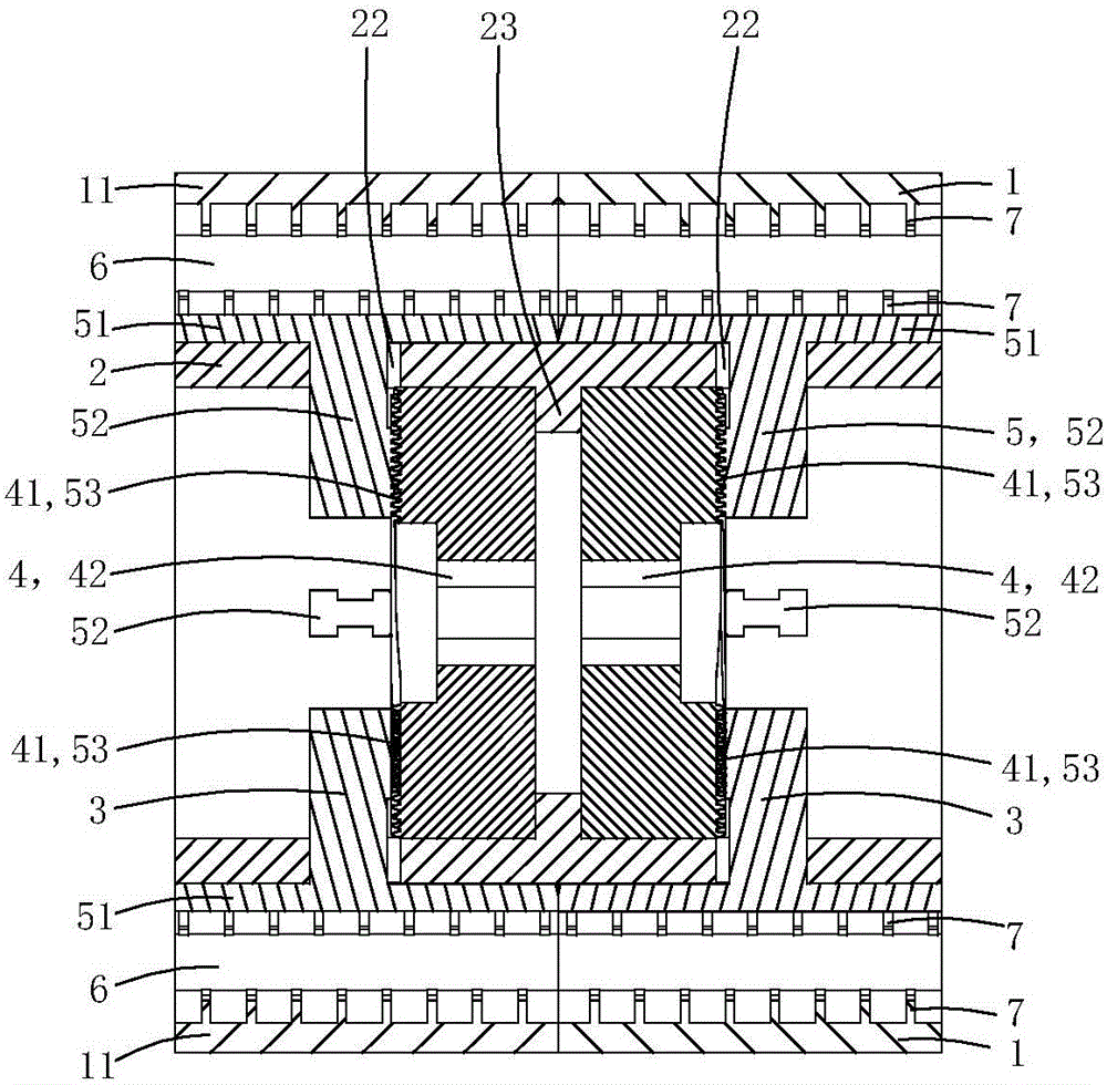
[0017] The tube wall of the core tube is provided with six radial limiting sliding holes 22, and each radial limiting sliding hole penetrates the core tube wall along the radial direction of the core tube; each radial limiting sliding hole is located in the axial direction of the core tube In the middle of the upper part, the radial cross-sectional shape of each radial limiting hole is an I-shape; the inner peripheral wall of the core tube is provided with an inwardly protruding annular stop 23. In this embodiment, the six radial limiting holes are divided into two groups, and the three radial limiting holes in each group are used to fit a corresponding set of pressing claw components.
[0018] Each set of crimping components is used to adapt to a correspondi...
Embodiment 2)
[0032] This embodiment is basically the same as the above-mentioned embodiment 1, the difference is: see Figure 5 with Image 6 As shown, at least one crimping piece 1 is provided with a mounting screw hole 15 penetrating the pressure plate part along the core tube radial direction; a temperature sensing device 8 is fixed in the mounting screw hole.
[0033] The temperature sensing device 8 includes a metal shell 81 made of a metal material and having a containing groove 811, a temperature sensor 82 arranged in the containing groove, and a spring 83 for pressing the temperature sensor on the bottom wall of the containing groove , Solenoid plug 84 for limit spring.
[0034] The end 812 of the metal shell close to the central axis of the core tube is provided with a heat conduction boss 813 used for puncture, and the end 814 of the metal shell far away from the central axis of the core tube is provided with an inner hexagonal screwing groove 815; There is an external thread 816 adap...
Embodiment 3)
[0042] This embodiment is basically the same as the above-mentioned embodiment 2, the difference lies in: see Figure 7 As shown, in this embodiment, a current transformer 9 is fixed on the outer peripheral wall of the crimping part, and the current transformer 9 includes a ring-shaped induction body 91 and an intelligent control module 92; the overall shape of the intelligent control module is also a ring; The sensing body 91 and the intelligent control module 92 are arranged side by side.
[0043] The inner peripheral wall of the intelligent control module 92 is provided with two electrical connection sleeves (not shown in the figure) protruding inward, and each electrical connection socket is inserted into a corresponding electrical connection sleeve, so that the temperature sensor and the intelligent control module The central control circuit is connected.
[0044] This embodiment can be used to clamp three-phase cables. At this time, this embodiment as a whole can be used as a...
PUM
 Abstract
Description
Claims
Application Information