Hydraulic hollow tube springback control method and device

A control method and hollow tube technology, applied in the field of pipe fitting parts manufacturing, can solve problems such as long modeling period of combined bends, difficulty in predicting springback trend, impact on product quality, etc., to eliminate springback, reduce wear, and improve dimensional accuracy Effect

Active Publication Date: 2016-08-24
SHANGHAI BAOSTEEL NEW TECH PARTS
View PDF6 Cites 2 Cited by
  • Summary
  • Abstract
  • Description
  • Claims
  • Application Information

AI Technical Summary

Problems solved by technology

In practice, since there are often multiple bending angles on the part, the springback calculation of the combined bending angle has the disadvantages of long modeling period, difficult prediction of springback trend, and poor result accuracy. On

Method used


Image

  • Hydraulic hollow tube springback control method and device
  • Hydraulic hollow tube springback control method and device
  • Hydraulic hollow tube springback control method and device

Examples


Embodiment 1

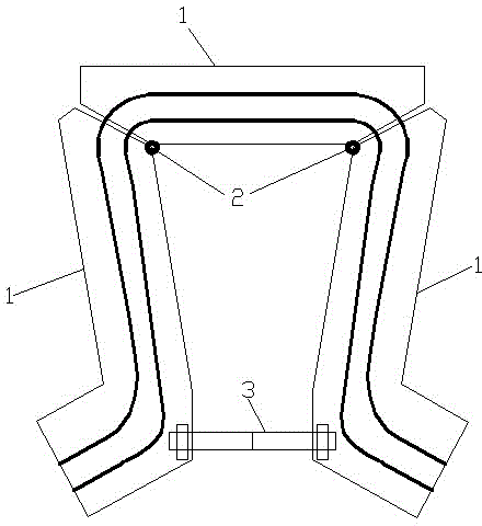
[0024] Such as image 3 As shown, a hydraulic hollow pipe springback control device is composed of several independent mold cavity sections 1, and two adjacent mold cavity sections 1 are hingedly connected by a rotating shaft 2, and the rotating shaft The axis of 2 is the rotation center corresponding to the bending part of the machined part, and the rebound adjustment mechanism 3 is arranged on the mold cavity section 1 .

[0025] In this embodiment, the mold cavity section 1 has three sections in total, and the three mold cavity sections 1 are sequentially spliced ​​to form two bends in the same direction, and the rebound adjustment mechanism 3 is arranged at two Between side mold cavity segments 1.

[0026] In order to cooperate with the three-stage structure in this embodiment, it is convenient to adjust the bending angle, such as Figure 4 As shown, the rebound adjustment mechanism 3 includes an adjustment screw 31 and a pair of adjustment nuts 32, and a pair of mold ca...


PUM


Abstract

The invention relates to the field of tube part manufacturing, in particular to a tubular hydraulic forming part machining method and device. The hydraulic hollow tube springback control method comprises the steps that the initial bent angle of a mold is set according to the preforming target angle of a part; the part is placed into the mold to be preformed; and the part is taken out of a mold cavity after being preformed, the actual bent angle of the part is measured, the bent angle of the mold is adjusted, and the new bent angle of the mold is the bent angle of the mold during final part machining. The hydraulic hollow tube springback control device is formed by combining a plurality of independent mold cavity sections. The axes of rotating shafts are rotation centers corresponding to the bent positions of the machined part. Each mold cavity section is provided with a springback adjusting mechanism. According to the tubular hydraulic forming part machining method and device, springback in the tube part forming process can be eliminated, the part springback amount does not need to be pre-calculated, and springback can be directly and flexibly adjusted through the device, so that the part development cycle in the early period is shortened, the hydraulic forming mold abrasion is reduced, and the size precision of the hydraulic forming part is improved.

Description

technical field [0001] The invention relates to the field of manufacturing pipe fittings, in particular to a processing method and device for tubular hydroforming parts. Background technique [0002] In the fields of aircraft, spacecraft and automobiles, reducing weight to save materials and energy in operation is one of the trends in the development of modern manufacturing technology. It is against this background that hydroforming was developed as a method for manufacturing hollow light-body structural parts. Advanced Manufacturing Technology. For most hydroformed tubular parts, qualified parts must be obtained after straight pipe bending, preforming, hydroforming, and cutting processes in sequence. In this process, for some parts with non-linear axes, it is necessary to bend the pipe first, and then pre-form the bent pipe to deform the part into a shape roughly the same as that of the hydroformed part, and then put it into the hydroforming mold for hydroforming . Durin...

Claims


Application Information

Patent Timeline
IPC IPC(8): B21D7/16B21D7/14B21D37/12
Inventor 苏海波蒋浩民陈新平王娜
Owner SHANGHAI BAOSTEEL NEW TECH PARTS
Why Eureka
Try Eureka