Suspension device for rear wheel

A suspension device and rear wheel technology, which is applied to axle suspension devices, bicycle accessories, transportation and packaging, etc., can solve the problems of high frame strength requirements, large lateral space of the body, and uncoordinated body proportions, so as to improve driving and riding. Comfort, design space improvement, vibration reduction effect

Inactive Publication Date: 2016-08-24
TAIZHOU LIMA ELECTRIC VEHICLE SCI & TECH
View PDF5 Cites 1 Cited by
  • Summary
  • Abstract
  • Description
  • Claims
  • Application Information

AI Technical Summary

Problems solved by technology

When the motor vehicle is driving, the bumps from the road will directly act on the wheels. Since the load of the motor vehicle is mainly concentrated on the rear wheels, and the rear fork is directly hard-connected to the frame, this bump will directly affect the frame. As a result, the overall comfort of motor vehicles in harsh environments is not good, and the strength requirements for the frame are also high.
[0003] In addition, the existing rear wheel suspensions all adopt double-sided rear chainstays plus bilateral shock absorbers. The double-sided rear chainstays take up a large amount of space on the side of the vehicle body, which affects the appearance, and the proportions of the vehicle body are uncoordinated. , The shock absorber is a three-point connection, triangular in shape, and the stability is not enough. The dynamic angle between the shock absorption axis and the horizontal ground is 70 degrees to 75 degrees. The ratio of the shock absorption compression stroke to the suspension stroke is between 0.75-0.8. These operating parameters of motor vehicles are caused by the existing structure, and these operating parameters of motor vehicles cannot well meet the requirements of driving comfort

Method used


Image

  • Suspension device for rear wheel
  • Suspension device for rear wheel
  • Suspension device for rear wheel

Examples


Embodiment Construction

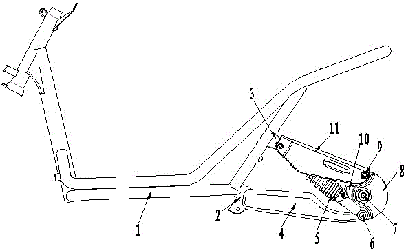
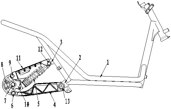
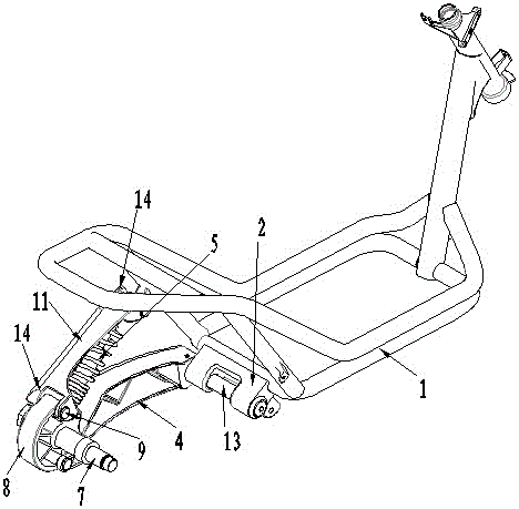
[0018] See figure 1 , 2 3. The rear wheel suspension device is applied to a motor vehicle, and is used to connect the rear wheel of the motor vehicle, so that the rear wheel is connected to the vehicle frame 1 in a suspended manner. The motor vehicle mainly includes motorcycles and electric vehicles.

[0019] The structure of this rear wheel suspension device comprises shock absorber 5 and wheel axle 7, and wheel axle 7 is assembled on rocker arm 8, and wheel axle 7 is used for assembling rear wheel, and one end of shock absorber 5 is hinged on vehicle frame 1, and the other end is hinged on On the rocker arm 8.

[0020] The structure of the rear wheel suspension device also includes an upper connecting arm 11 and a lower connecting arm 4, the upper connecting arm 11 and the lower connecting arm 4 are plate-shaped, the upper connecting arm 11 and the shock absorber 5 are all obliquely arranged, and the lower connecting arm 4 are set in an approximately horizontal orientation...


PUM


Abstract

The invention discloses a suspension device for a rear wheel. The suspension device is arranged on the rear side of a frame and is used for linking the rear wheel. The suspension device comprises a wheel shaft and a shock absorber, wherein a rocker arm is assembled on the wheel shaft; the shock absorber is arranged on one side of the rocker arm; one end of the shock absorber is hinged on the frame while the other end is hinged on the rocker arm; one end of an upper linking arm is hinged on the frame while the other end is hinged on the rocker arm; one end of a lower linking arm is hinged on the frame while the other end is hinged on the rocker arm; the shock absorber and the upper linking arm are both arranged in an inclined form; the upper linking arm and the shock absorber are located above the lower linking arm; the shock absorber is located between the upper linking arm and the lower linking arm; one ends of the upper linking arm and the lower linking arm are separated at a hinge point on the frame. The suspension device has a simple structure; the design of the suspension device is different from the design of the prior art; the motor vehicle can more efficiently adapt to the driving requirements on different pavements; the driving and taking comfort of the motor vehicle are excellent.

Description

technical field [0001] The invention relates to a frame device of a motor vehicle, in particular to a suspension device for connecting rear wheels to the frame. Background technique [0002] The wheels of motor vehicles such as electric vehicles and motorcycles are all connected to the frame. Specifically, the rear wheels of the motor vehicle are formed with a rear fork on the frame, and the axles of the rear wheels are fixed on the rear fork. Located in the fork of the rear chainstay. A shock absorber is arranged between the seat cushion and the rear chainstay of the motor vehicle, and the shock absorber is used to provide a certain damping effect for the driver and passenger, so as to improve the driving comfort of the driver and passenger. When the motor vehicle is driving, the bumps from the road will directly act on the wheels. Since the load of the motor vehicle is mainly concentrated on the rear wheels, and the rear fork is directly hard-connected to the frame, this ...

Claims


Application Information

Patent Timeline
Patent Type & Authority Applications(China)
IPC IPC(8): B62K25/00B62K25/20
CPCB62K25/005B62K25/20
Inventor 张中华彭浩平应光捷
Owner TAIZHOU LIMA ELECTRIC VEHICLE SCI & TECH
Why Eureka
Try Eureka