Bridge shock reduction and isolation supporting base and cable-stayed bridge and suspension bridge supporting structure

A technology for supporting structures and seismic isolation, applied in bridges, bridge construction, bridge parts, etc., can solve problems such as poor seismic performance, reduce design difficulty and construction cost, extend the lateral vibration period of the structure, and reduce the effect of seismic response.

Active Publication Date: 2016-08-24
SHANDONG TRAFFIC PLANNING DESIGN INST
View PDF8 Cites 20 Cited by
  • Summary
  • Abstract
  • Description
  • Claims
  • Application Information

AI Technical Summary

Problems solved by technology

[0004] In order to solve the deficiencies of the prior art, the present invention provides a bridge bearing, which is used to solve the problem of poor seismic performance of the existing bearing in the transverse direction

Method used


Image

  • Bridge shock reduction and isolation supporting base and cable-stayed bridge and suspension bridge supporting structure
  • Bridge shock reduction and isolation supporting base and cable-stayed bridge and suspension bridge supporting structure
  • Bridge shock reduction and isolation supporting base and cable-stayed bridge and suspension bridge supporting structure

Examples


Embodiment 1

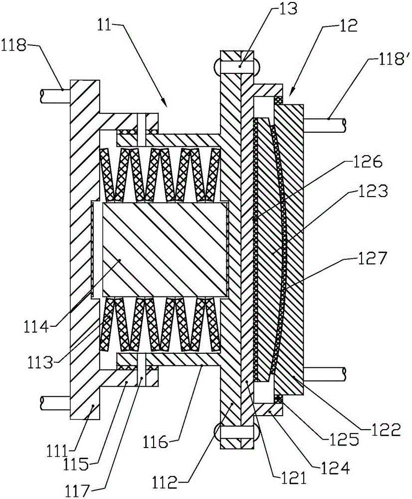
[0024] Embodiment 1, the specific structure is as follows: the disc spring assembly 11 includes a first plate 111, a second plate 112, a spring plate 113 and a guide column 114, wherein the first plate 111 and the second plate are thick steel plates oppositely arranged, A first sleeve 115 extending toward the second plate is provided on the first plate 111, a second sleeve 116 extending toward the first plate is provided on the second plate 112, and the first sleeve and the second sleeve They are overlapped with each other and connected with shear pins 117, and multiple leaf springs 113 are stacked between the first plate and the second plate and in the space enclosed by the first sleeve and the second sleeve, wherein the spring plates A guide post is placed at the center of the guide post 114, and grooves and rubber pads are provided on the surfaces of the first plate and the second plate that are matched at the ends of the guide post 114 for buffering.

[0025] A locking mem...

Embodiment 2

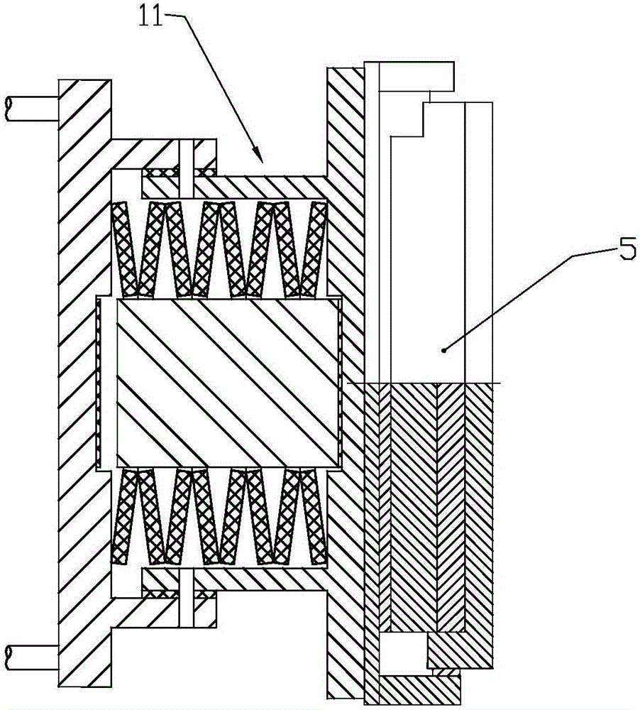
[0030] Embodiment two, refer to Figure 5 ,

[0031] A C-shaped mild steel damper 4 is arranged between the first plate and the second plate, wherein the C-shaped mild steel damper is evenly arranged in the area between the first plate and the second plate. As an optimal form, the above-mentioned C-shaped mild steel damper 4 is a C-shaped mild steel plate, with hinged ends at both ends, which are hinged with the above-mentioned first plate and the second plate by means of a hinge 41, And set the preload to form an elastic support. Furthermore, the above-mentioned C-shaped mild steel plate can be formed by stacking multiple pieces, which has greater supporting strength.

[0032] In this embodiment, the second difference from the first embodiment is that the end of the guide column 114 is permanently fixedly connected with the second plate, such as welded, to form an integral structure that can be linked with the second plate. Avoid guide posts floating.


PUM


Abstract

The invention discloses a bridge shock reduction and isolation supporting base and a cable-stayed bridge and suspension bridge supporting structure. The bridge supporting base comprises a left part and a right part, the left part is a transverse disk spring assembly, the right part is a transverse one-way movable supporting base, the left part and the right part are connected in series and connected into an integrated structure through a connecting piece, and a plurality of C-type mild steel dampers can be evenly arranged between a first plate and a second plate in the circumferential direction. The invention discloses application of the bridge supporting base to a cable-stayed bridge and a suspension bridge. After the bridge shock reduction and isolation supporting base is adopted, the transverse vibration period of the structure can be effectively prolonged, and deformation of a disk spring can also consume part of earthquake energy, so that bridge tower transverse seismic response can be remarkably reduced, the amplitude reaches 20-30%, and design difficulty and building cost are effectively reduced.

Description

technical field [0001] The invention relates to a bridge bearing, in particular to a bridge shock-absorbing and isolating bearing and the applied cable-stayed bridge and suspension bridge. Background technique [0002] At present, for cable-stayed bridges and suspension bridge structures, since the main girder is in a laterally restrained state at the bridge tower, and the lateral seismic force of the main girder will be directly transmitted to the bridge tower through the beam under the action of an earthquake, the transverse seismic force of the bridge tower Usually, the design can only be carried out by using the traditional seismic design method. In order to keep the bridge tower in an elastic state under earthquake action, it can only be realized by increasing the section size and the amount of reinforcement. [0003] The traditional seismic design method needs to rely on the strength, ductility and energy dissipation capacity of the structure itself to resist the earth...

Claims


Application Information

Patent Timeline
Patent Type & Authority Applications(China)
IPC IPC(8): E01D19/04E01D11/00
CPCE01D11/00E01D19/041
Inventor 张常勇王志英王宏博王洺鑫董晓马雪媛
Owner SHANDONG TRAFFIC PLANNING DESIGN INST
Why Eureka
Try Eureka