
Air compressor rotor

A compressor rotor and rotor disk technology, applied in the field of compressors, to achieve the effects of reducing gas leakage, easy to use, and improving rigidity

Active Publication Date: 2016-08-24
AECC SHENYANG ENGINE RES INST
View PDF8 Cites 2 Cited by
  • Summary
  • Abstract
  • Description
  • Claims
  • Application Information

AI Technical Summary

Problems solved by technology

[0003] The object of the present invention is to provide a compressor rotor to solve or at least alleviate at least one of the problems in the background art

Method used


Image

  • Air compressor rotor
  • Air compressor rotor

Examples


Embodiment Construction

[0018] In order to make the objectives, technical solutions and advantages of the present invention clearer, the technical solutions in the embodiments of the present invention will be described in more detail below in conjunction with the drawings in the embodiments of the present invention. In the drawings, the same or similar reference numerals denote the same or similar elements or elements having the same or similar functions throughout. The described embodiments are some, but not all, embodiments of the invention. The embodiments described below by referring to the figures are exemplary and are intended to explain the present invention and should not be construed as limiting the present invention. Based on the embodiments of the present invention, all other embodiments obtained by persons of ordinary skill in the art without creative efforts fall within the protection scope of the present invention. Embodiments of the present invention will be described in detail below ...


PUM


Abstract

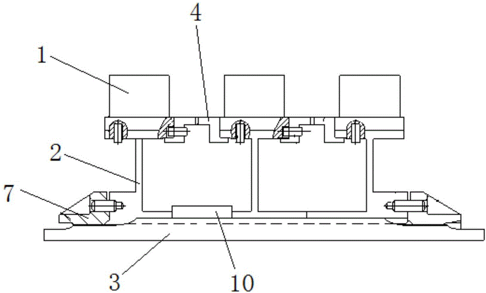
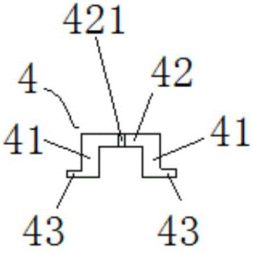
The invention discloses an air compressor rotor and relates to the technical field of air compressors. The air compressor rotor comprises rotor blades (1), rotor plates (2), a rotor shaft (3) and locking nuts (7). At least two rotor plates (2) are arranged. The rotor shaft (3) is sleeved with the fixing ends of the rotor plates (2). Blade installing ends are used for installing the rotor blades (1). An intermediary ring (4) is arranged between the blade installing ends of the two rotor plates (2) and makes contact with the two rotor plates (2) in the axial direction of the rotor shaft (3). The blade installing end of at least one rotor plate (2) is connected with the intermediary ring (4). The fixing ends of the multiple rotor plates (2) are fixed through the locking nuts (7) in the axial direction of the rotor shaft (3). The air compressor rotor has the advantages that the air compressor rotor comprises the multiple rotor plates, the rotor plates can be replaced and maintained individually, and use is convenient.

Description

technical field [0001] The invention relates to the technical field of compressors, in particular to a compressor rotor. Background technique [0002] The connection of the compressor rotor mainly solves the problems of disk connection, disk shaft connection, blade and disk connection, etc. Disk connection and disk shaft connection can be divided into detachable and non-detachable. The detachable connection includes short bolt connection, long bolt connection, circular arc end tooth plus center tie rod connection and sleeve tooth connection; the non-detachable connection has two methods: pin connection and welding connection. There are three ways of connection between the blade and the disk: the overall blade disk, the axial tenon and the circumferential tenon. However, in the existing compressor rotors, the rotor disk is an integral structure. Whether it is detachable or non-detachable, as long as one part of the rotor disk is damaged, the entire rotor disk needs to be re...

Claims


Application Information

Patent Timeline
Patent Type & Authority Applications(China)
IPC IPC(8): F04D29/28F04D29/60
CPCF04D29/284F04D29/601
Inventor 张岩印雪梅
Owner AECC SHENYANG ENGINE RES INST
Learn More