
Backlight module and liquid-crystal display device

A backlight module and backlight module technology, applied in optics, nonlinear optics, instruments, etc., can solve the problems of thick backlight module thickness, inability to achieve ultra-thin design, and inability to achieve two-dimensional brightness control, saving mixed light effect of space

Active Publication Date: 2016-08-24
TCL CHINA STAR OPTOELECTRONICS TECH CO LTD
View PDF5 Cites 6 Cited by
  • Summary
  • Abstract
  • Description
  • Claims
  • Application Information

AI Technical Summary

Problems solved by technology

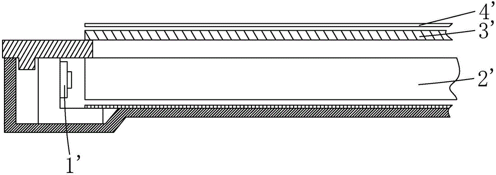
However, the traditional direct-type backlight module and side-type backlight module have their own advantages and disadvantages due to their different structures, and both cannot take into account the ultra-thin design and the local backlight adjustment design at the same time.
[0007] For the direct-lit backlight module, since the LED light sources are arranged in an array type, it is easy to realize multi-zone independent brightness control, that is, local backlight adjustment and HDR effect display can be realized; A certain light mixing space needs to be reserved between the diffusion plate and the diffuser, which will inevitably result in a thicker backlight module, which cannot achieve ultra-thin design
[0008] As for the side-type backlight module, since the light source is used to enter the light from the side, and the light guide plate is used as the carrier of light transmission, the ultra-thin design can be realized. Two-dimensional brightness control cannot be realized, so the effect of local backlight adjustment of multiple partitions cannot be realized

Method used


Image

  • Backlight module and liquid-crystal display device
  • Backlight module and liquid-crystal display device
  • Backlight module and liquid-crystal display device

Examples


Embodiment Construction

[0035] In order to further illustrate the technical means adopted by the present invention and its effects, the following describes in detail in conjunction with preferred embodiments of the present invention and accompanying drawings.

[0036] see image 3 , the present invention firstly provides a backlight module, comprising: several backlight modules 11 arranged in a matrix, a diffusion sheet 20 arranged above the several backlight modules 11, an optical optical module arranged above the diffusion sheet 20 The diaphragm group 30 and the reflection sheet 40 disposed under the plurality of backlight modules 11 .

[0037] Specifically, such as Figure 8 As shown, each backlight module 11 includes four backlight units 12 arranged in a 2×2 matrix.

[0038] Specifically, such as Figure 4-5 As shown, each backlight unit 12 includes a light guide plate 121 and a light bar 122 disposed on one side of the light guide plate 121 , and the light bar 122 includes a plurality of LEDs...


PUM


Abstract

The invention provides a backlight module and a liquid-crystal display device. The backlight module comprises a plurality of backlight module bodies arranged in a matrix mode and diffusion sheets arranged above the backlight module bodies, wherein each backlight module body comprises four backlight units arranged in a 2*2 matrix mode, and each backlight unit comprises a light guide plate and a lamp strip arranged on one side of the light guide plate. By the adoption of the backlight module body combination mode, on the one hand, independent brightness control of multiple partitions can be achieved, and the backlight module can be used for local backlight adjustment and HDR effect showing compared with a traditional lateral incidence type backlight module; on the other hand, the light mixing space is saved by utilizing the emergent light uniformizing effects of the light guide plates compared with a traditional direct-lit type backlight module, and accordingly ultra-thin design can be achieved. The liquid-crystal display device adopts the backlight module and can simultaneously achieve the ultra-thin design and local backlight adjustment design.

Description

technical field [0001] The invention relates to the technical field of liquid crystal display, in particular to a backlight module and a liquid crystal display device. Background technique [0002] A liquid crystal display (Liquid Crystal Display, LCD) has many advantages such as a thin body, power saving, and no radiation, and has been widely used. Such as: LCD TV, mobile phone, personal digital assistant (PDA), digital camera, computer screen or notebook computer screen, etc., occupy a dominant position in the field of flat panel display. Most of the liquid crystal display devices currently on the market are backlight liquid crystal display devices, which include a liquid crystal panel and a backlight module (Backlight Module). Usually, the structure of the liquid crystal panel is composed of a color filter substrate (Color Filter), a thin film transistor array substrate (Thin FilmTransistor Array Substrate, TFT Array Substrate), and a liquid crystal layer (Liquid Crystal...

Claims


Application Information

Patent Timeline
Patent Type & Authority Applications(China)
IPC IPC(8): G02F1/13357
CPCG02F1/133615
Inventor 贺虎
Owner TCL CHINA STAR OPTOELECTRONICS TECH CO LTD
Learn More