Lead shockproof device

A technology of anti-vibration device and wire, which is applied in the direction of mechanical vibration attenuation device, etc., can solve the problem that the anti-vibration effect of wire anti-vibration device is not ideal, and achieve the effect of reducing damage

Inactive Publication Date: 2016-08-24
TIANJIN HUADIAN ELECTRIC EQUIP FACTORY
View PDF0 Cites 0 Cited by
  • Summary
  • Abstract
  • Description
  • Claims
  • Application Information

AI Technical Summary

Problems solved by technology

[0004] The purpose of the present invention is to solve the above technical problems and provide a wire shockproof device, which aims to solve the technical problem that the shockproof effect of the existing wire shock absorbers is not ideal

Method used


Image

  • Lead shockproof device
  • Lead shockproof device

Examples


Embodiment Construction

[0012] Hereinafter, the substantial features and advantages of the present invention will be further described with reference to examples, but the present invention is not limited to the listed embodiments.

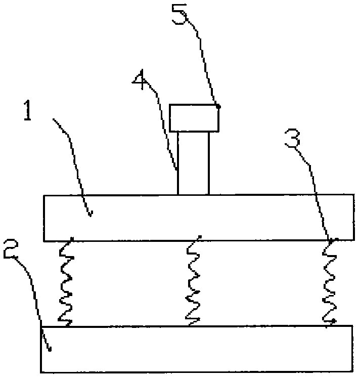
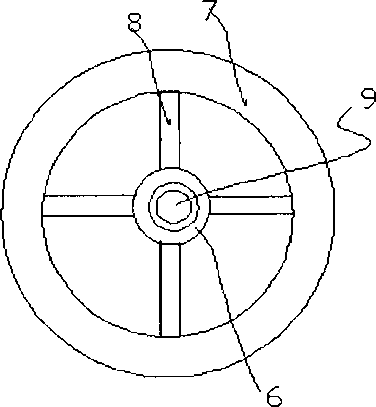
[0013] see figure 1 , 2 As shown, a wire shockproof device includes a first shockproof disk 1 and a second shockproof disk 2 with the same structure. The first shockproof disk 1 and the second shockproof disk are connected along the periphery of the 2 by a plurality of steel springs Then, the first and second anti-vibration discs 1 include a central connecting seat 6, an outer connecting ring 7 is arranged outside the central connecting seat 6, and the central connecting seat 6 and the outer connecting ring 7 are in a radial shape. The connection is provided with a plurality of elastic rods 8 .

[0014] It should be noted that the outer connecting ring 7 is provided with a spring hanging ring or a hanger, and the spring 3 connects the two shockproof disks through the sp...


PUM


Abstract

The invention relates to a lead shockproof device which comprises a first shockproof disk and a second shockproof disk of the same structure. The first shockproof disk is connected with the second shockproof disk via multiple steel springs along the circumference, the first shockproof disk and the second shockproof disk comprises a central connecting seat, an external connecting ring is arranged outside the central connecting seat, and multiple elastic rods are connected and arranged between the central connecting seat and the external connecting ring in a radial shape. Vibration and swinging of overhead electric lines can be absorbed or weakened by the two shockproof disks and the connecting springs, the shockproof effect is good, and damage on leads is effectively reduced.

Description

technical field [0001] The invention belongs to the technical field of anti-vibration hammers, and in particular relates to a wire anti-vibration device. Background technique [0002] At present, on high-voltage transmission lines, overhead wires are subjected to meteorological conditions such as wind and ice, which will generate vibration and galloping with high frequency and small amplitude, thus affecting the service life of overhead wires. In power transmission, anti-vibration hammers are generally used. Absorbs or dampens vibration and galloping of overhead power lines. [0003] Most of the prior art anti-vibration hammers absorb shock by swinging the columnar pendulum at both ends of the connecting rod. Such a connection structure of the anti-vibration hammer can easily cause the hammer body to fall off for a long time, which may cause accidents. SUMMARY OF THE INVENTION [0004] The purpose of the present invention is to solve the above technical problem and provid...

Claims


Application Information

Patent Timeline
Patent Type & Authority Applications(China)
IPC IPC(8): H02G7/14
Inventor 李文芳
Owner TIANJIN HUADIAN ELECTRIC EQUIP FACTORY
Why Eureka
Try Eureka