Cowl structure
A kind of enclosure and structure technology, applied in the field of front enclosure structure, can solve the problem of increasing the number of parts and achieve the effect of suppressing pressing
- Summary
- Abstract
- Description
- Claims
- Application Information
AI Technical Summary
Problems solved by technology
Method used
Image

Examples
Embodiment 1
[0030] First, Embodiment 1 of the present invention will be described based on the drawings.
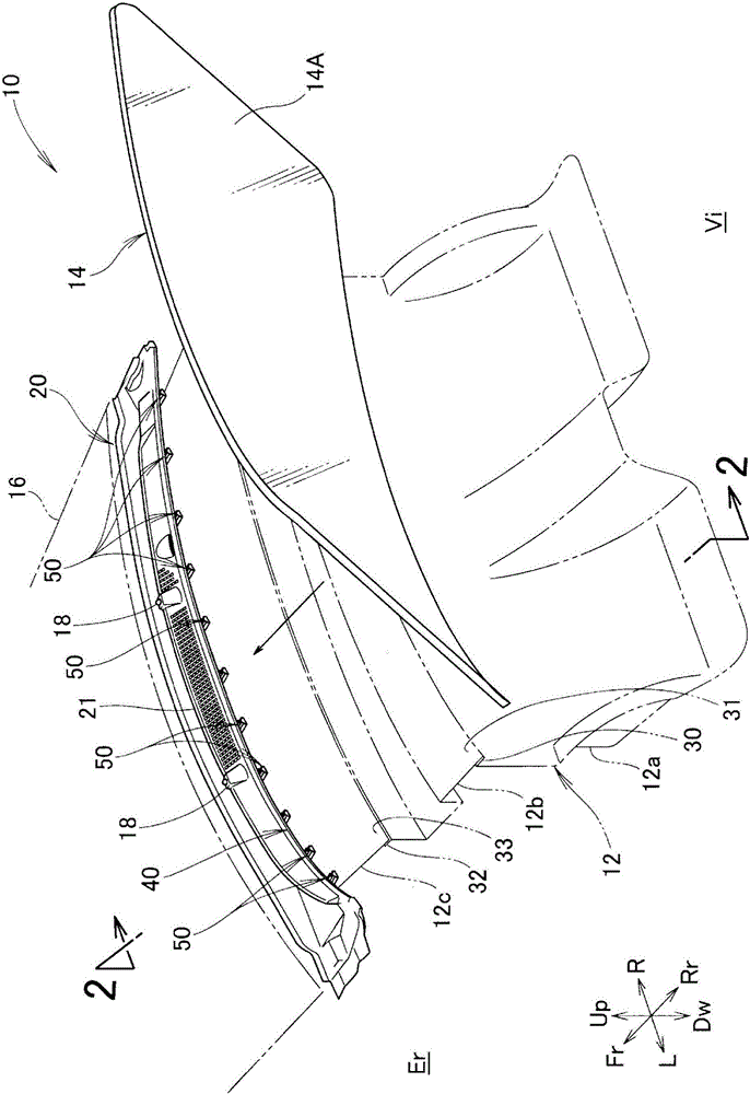
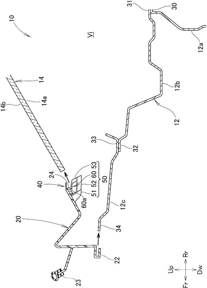
[0031] refer to figure 1 . On the front portion of the vehicle 10, a dashboard panel 12 is provided to partition the passenger compartment Vi from the engine compartment Er within the range in the vehicle width direction. A resin-made cowl main body 20 is connected to an upper portion of the instrument panel panel 12 over a range in the vehicle width direction. The lower end of the windshield 14 is supported by the cowl main body 20 . In front of the cowl main body 20 is provided a swingable engine hood 16 capable of opening and closing above the engine compartment Er.
[0032] The dashboard panel 12 is constituted by: a dashboard lower panel 12a constituting the front wall of the passenger compartment Vi; a dashboard upper panel 12b joined to the upper portion of the dashboard lower panel 12a and extending forward of the vehicle; An end portion of the upper panel 12b is joined ...
Embodiment 2
[0048] Next, based on Figure 6 The lip 60A of Example 2 will be described.
[0049] Depending on how the direction from the base end of the first lip 61A toward the front end is taken, or how the length of the first lip 61A is taken, there may be a case where the windshield is inserted between the outer glass abutting portion 40 and the lip 60A. , the entire surface of the second lip 62A (at least a part of the upper surface of the second lip 62A) is in contact with the windshield 14 .
[0050] In this case, the tip of the second lip portion 62A having high hardness is also in contact with the windshield 14 , but it also contacts the windshield 14 including other parts. Therefore, the contact of the second lip portion 62A with the windshield 14 becomes soft compared to the case where the windshield 14 is pressed only by the front end. That is, by making the portion other than the front end 60a of the lip 60A having high hardness come into contact with the windshield 14 to i...
Embodiment 3
[0052] Next, based on Figure 7 The lip 60B of Example 3 will be described.
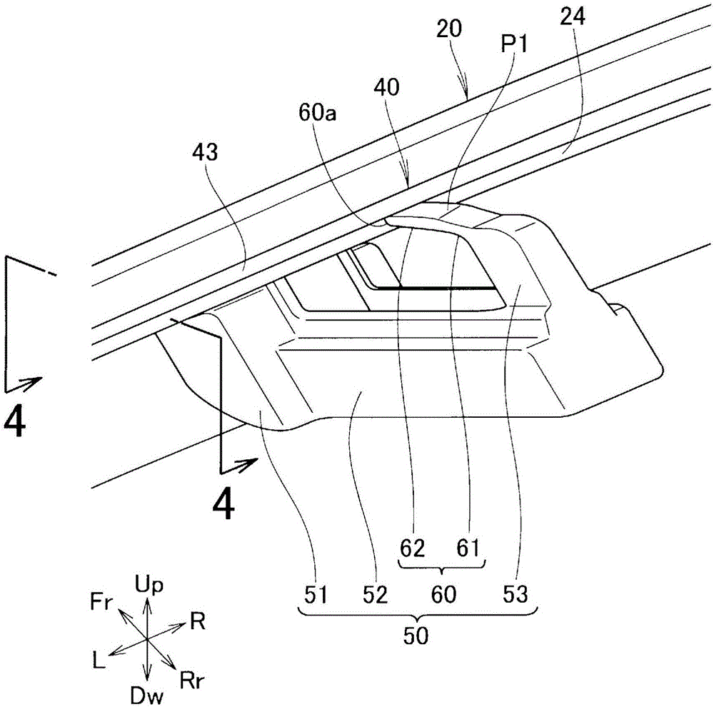
[0053] The lip 60B has a curved shape (substantially U-shaped) such as an arc. When the first lip 61 and the second lip 62 are bent like the lip 60 of the first embodiment, a corner is formed at the boundary thereof, and the windshield 14 is pressed by the corner. On the other hand, both the first lip 61B and the second lip 62B are curved. Therefore, the pressing by the curved surface centering on the inflection point P2 is configured, and the touch of the lip 60B to the windshield 14 becomes soft. Even in this case, the effects specified by the present invention can be obtained.
[0054] In addition, the outer glass contact portion 40 may also be formed by two-color molding in which different materials are combined and integrally molded. When the outer glass contact piece 43 is formed of a material softer than the main body portion 41 , the adhesion of the outer glass contact piece 43 to the wind...
PUM
 Abstract
Description
Claims
Application Information
 - R&D
- Intellectual Property
- Life Sciences
- Materials
- Tech Scout
- Unparalleled Data Quality
- Higher Quality Content
- 60% Fewer Hallucinations
Browse by: Latest US Patents, China's latest patents, Technical Efficacy Thesaurus, Application Domain, Technology Topic, Popular Technical Reports.
© 2025 PatSnap. All rights reserved.Legal|Privacy policy|Modern Slavery Act Transparency Statement|Sitemap|About US| Contact US: help@patsnap.com