Unlock instant, AI-driven research and patent intelligence for your innovation.
A split filter
What is Al technical title?
Al technical title is built by PatSnap Al team. It summarizes the technical point description of the patent document.
A filter and shunt-type technology, which is applied in the direction of fixed filter element filter, filter separation, passing components, etc., can solve the problems of shortening service life and other problems, achieve the effect of reducing impact force, strengthening overall strength, and convenient disassembly and installation
Active Publication Date: 2018-08-03
浙江博凡核工程技术有限公司
View PDF6 Cites 0 Cited by
Summary
Abstract
Description
Claims
Application Information
AI Technical Summary
This helps you quickly interpret patents by identifying the three key elements:
Problems solved by technology
Method used
Benefits of technology
Problems solved by technology
[0004] The purpose of the present invention is to overcome the shortcomings of the above-mentioned prior art and provide a split filter, which aims to solve the problem that the filter element in the prior art is easily affected by the fast-flowing working medium during use and shortens the service life. technical issues
Method used
Image
Click on the blue label to locate the original text in one second.
Reading with bidirectional positioning of images and text.
Examples
Embodiment Construction
[0020] 为使本发明的目的、技术方案和优点更加清楚明了,下面通过附图中及实施例,对本发明进行进一步详细说明。 However, it should be understood that the specific embodiments described here are only used to explain the present invention, and are not intended to limit the scope of the present invention. Also, in the following description, descriptions of well-known structures and techniques are omitted to avoid unnecessarily obscuring the concept of the present invention.
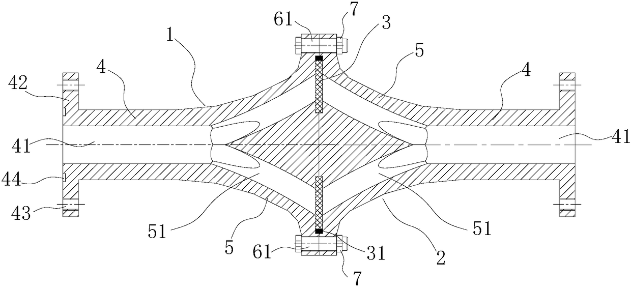
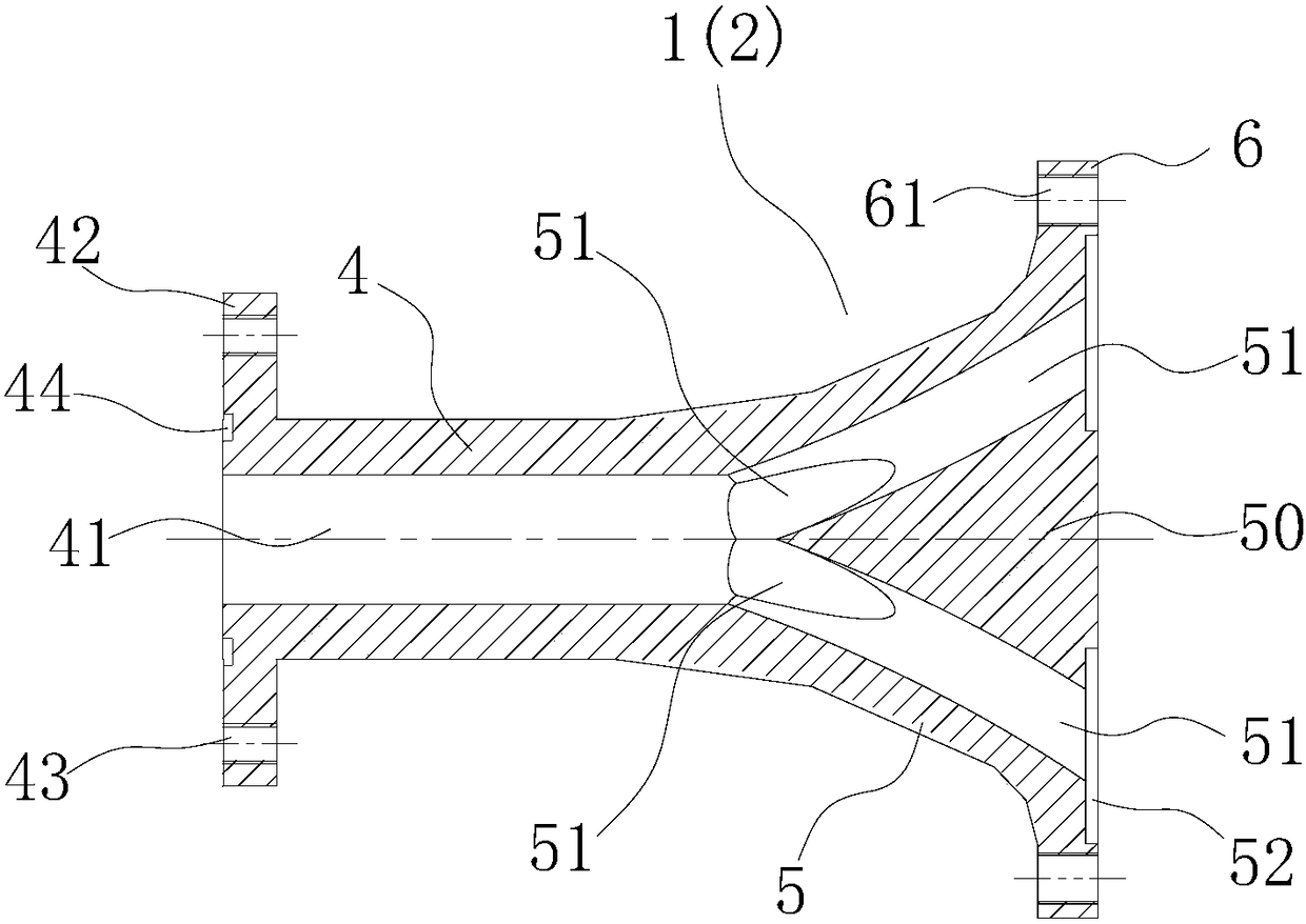
[0021] refer to Figure 1 to Figure 4 ,本发明实施例提供一种分流式过滤器,包括分流体1、汇流体2和环形滤片3,所述的分流体1与汇流体2结构相同且对称安装连接,所述的分流体1和汇流体2均由总流管段4、分流管段5和法兰凸缘6组成,所述的总流管段4、分流管段5和法兰凸缘6三者为一体结构,所述的分流管段5为圆台结构,小端面与总流管段4连接,大端面的外周与法兰凸缘6连接,所述的总流管段4内设置有总流通道41,所述的分流管段5内设置有分流锥50和若干分流通道51,所述的分流管段5的大端面上开设有滤片嵌槽52,所述的分流体1与汇流体2连接时,分流体1的分流管段5大端面与汇流体2的分流管段5大端面紧密贴合,分流体1上的分流通道51与汇流体2上的分流通道51相对应,且分流体1上的滤片嵌槽52与汇流体2上的滤片嵌槽52形成滤片安装槽,所述的滤片安装槽内安装环形滤片3。
PUM
Abstract
The invention discloses a flow-dividing type filter which comprises a flow divider, a confluence component and an annular filter disc, wherein the flow divider and the confluence component are the same in structure and are symmetrically mounted and connected; each of the flow divider and the confluence component is composed of a total flow pipe section, a flow-dividing pipe section and a flange, which have an integrated structure; each flow-dividing pipe section has a circular platform structure; the small end surface of each flow-dividing pipe section is connected with the corresponding total flow pipe section while the periphery of the big end surface of each flow-dividing pipe section is connected with the corresponding flange; a total flow channel is arranged in each total flow pipe section; a flow-dividing cone and a plurality of flow-dividing channels are arranged in each flow-dividing pipe section; a filter disc embedding slot is formed in the big end surface of each flow-dividing pipe section; when the flow divider is connected with the confluence component, the filter disc embedding slot in the flow divider and the filter disc embedding slot in the confluence component form a filter disc mounting slot; the annular filter disc is mounted in the filter disc mounting slot. The flow-dividing type filter is reasonable in structure. The manner of flow dividing, filtering and confluence in sequence is adopted, so that the service life of the filter disc is greatly prolonged.
Application Information
Patent Timeline
Application Date:The date an application was filed.
Publication Date:The date a patent or application was officially published.
First Publication Date:The earliest publication date of a patent with the same application number.
Issue Date:Publication date of the patent grant document.
PCT Entry Date:The Entry date of PCT National Phase.
Estimated Expiry Date:The statutory expiry date of a patent right according to the Patent Law, and it is the longest term of protection that the patent right can achieve without the termination of the patent right due to other reasons(Term extension factor has been taken into account ).
Invalid Date:Actual expiry date is based on effective date or publication date of legal transaction data of invalid patent.

